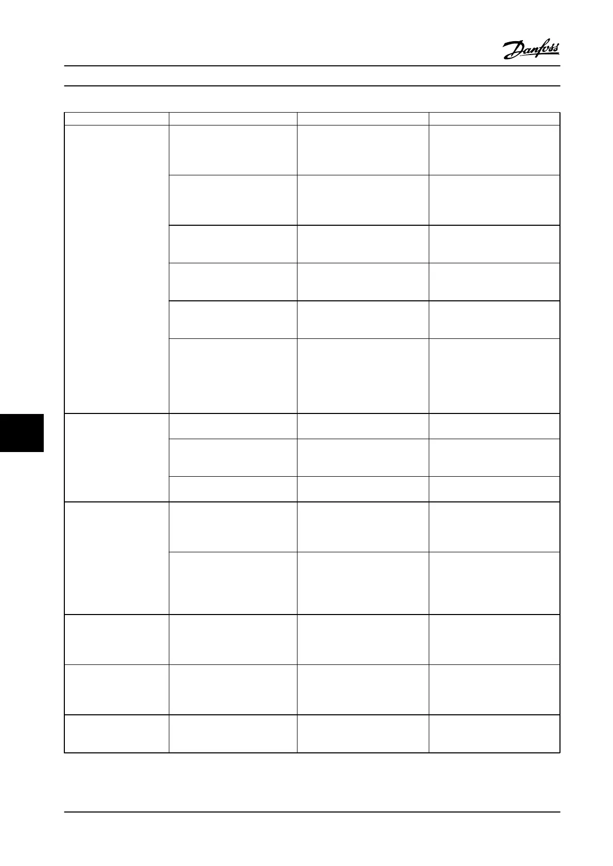
Symptom Possible Cause Test Solution
Motor not running
Service switch open or missing
motor connection
Check if the motor is connected
and the connection is not
interrupted (by a service switch or
other device).
Connect the motor and check the
service switch.
No line power with 24 V DC
option card
If the display is functioning but no
output, check that line power is
applied to the adjustable frequency
drive.
Apply line power to run the unit.
LCP Stop Check if [Off] has been pressed. Press [Auto On] or [Hand On]
(depending on operation mode) to
run the motor.
Missing start signal (Standby)
Check 5-10 Terminal 18 Digital Input
for correct setting for terminal 18
(use default setting).
Apply a valid start signal to start
the motor.
Motor coast signal active
(Coasting)
Check 5-12 Coast inv. for correct
setting for terminal 27 (use default
setting).
Apply 24 V on terminal 27 or
program this terminal to No
operation.
Wrong reference signal source Check reference signal: Local,
remote or bus reference? Preset
reference active? Terminal
connection correct? Scaling of
terminals correct? Reference signal
available?
Program correct settings. Check
3-13 Reference Site. Set preset
reference active in parameter
group 3-1* References. Check for
correct wiring. Check scaling of
terminals. Check reference signal.
Motor running in wrong
direction
Motor rotation limit
Check that 4-10 Motor Speed
Direction is programmed correctly.
Program correct settings.
Active reversing signal Check if a reversing command is
programmed for the terminal in
parameter group 5-1* Digital inputs.
Deactivate reversing signal.
Wrong motor phase connection
See chapter 3.7 Check Motor
Rotation in this manual.
Motor is not reaching
maximum speed
Frequency limits set wrong
Check output limits in 4-13 Motor
Speed High Limit [RPM], 4-14 Motor
Speed High Limit [Hz] and 4-19 Max
Output Frequency.
Program correct limits.
Reference input signal not scaled
correctly
Check reference input signal
scaling in 6-* Analog I/O mode and
parameter group 3-1* References.
Reference limits in parameter
group 3-0* Reference limits.
Program correct settings.
Motor speed unstable
Possible incorrect parameter
settings
Check the settings of all motor
parameters, including all motor
compensation settings. For closed-
loop operation, check PID settings.
Check settings in parameter group
1-6* Analog I/O mode. For closed-
loop operation, check settings in
parameter group 20-0* Feedback.
Motor runs rough
Possible over-magnetization Check for incorrect motor settings
in all motor parameters.
Check motor settings in parameter
groups 1-2* Motor data, 1-3* Adv
motor data, and 1-5* Load indep.
setting.
Motor will not brake.
Possible incorrect settings in the
brake parameters. Possible too
short ramp-down times.
Check brake parameters. Check
ramp time settings.
Check parameter group 2-0* DC
brake and 3-0* Reference limits.
Basic Troubleshooting Instruction Manual
74 Danfoss A/S © Rev. 2014-02-10 All rights reserved. MG16E222
99
 Loading...


