VLT
®
FCD Series
Programming, FCD
300
Description of choice:
Set the required ramp time.
212 Quick-stop ramp-down time
(Q STOP RAMP TIME)
Value:
0.02 - 3600.00 sec.
✭ 3.00 sec
Function:
The quick-stop ramp-down time is the deceleration
time from the rated motor frequency to 0 Hz, provided
no overvoltage arises in the inverter because of
generating operation of the motor, or if the generated
current exceeds the current limit in parameter 221
Current limit I
LIM
. Quick-stop is activated via one of
the digital inputs or the serial communication.
Description of choice:
Set the required ramp-down time.
213 Jog frequency
(JOG FREQUENCY)
Value:
0.0 - Par. 202 Output frequency high limit, f
MAX
✭ 10.0 Hz
Function:
Jog frequency f
JOG
means a fixed output frequency
that the frequency converter supplies to the motor
when the Jog function is activated. Jog can be
activated via the digital inputs, serial communication
or via the LCP control panel, on the condition that
this is active in parameter 015 Local jog.
Description of choice:
Set the required frequency.
■ Reference function
The example shows how the resulting reference is
calculated when Preset references is used together
with Sum and Relative in parameter 214 Reference
function. The formula for the calculation of the
resulting reference can be seen in the section
entitled All about the FCD 300. See also the
drawing in Handling of references.
The following parameters are preset:
Par. 204 Minimum reference 10 Hz
Par. 205 Maximum reference 50 Hz
Par. 215 Preset reference 15 %
Par. 308 Term.53, Analogue input Reference
Par. 309 Term.53, min. sc aling 0V
Par. 310 Term.53, max. scaling 10 V
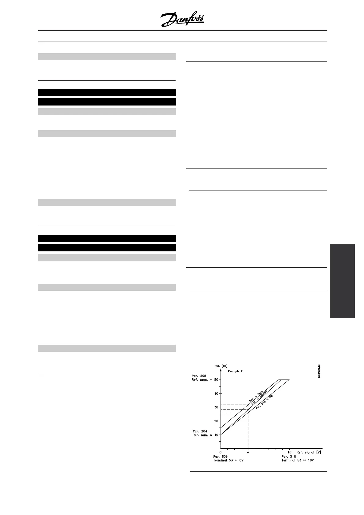
When parameter 214 Reference function is set to Sum
[0] one of the preset Preset references(par. 215-218) is
added to the external references as a percentage of the
reference range. If terminal 53 is applied an analogue
input voltage of 4 Volt will be the resulting reference:
Par. 214 Reference function =Sum[0]:
Par. 204 Minimum reference 10.0 Hz
Reference contribution at 4 Volt 16.0 Hz
Par. 215 Preset reference 6.0 Hz
Resulting reference 32.0 Hz
When parameter 214 Reference function is set
to Relative [1] the defined Preset references (par.
215-218) are added as a percentage of the total
of the present external references. If terminal
53 is applied to an analogue input voltage of 4
Volt the resulting reference will be:
Par. 214 Reference function = Relative [1]:
Par. 204 Minimum reference 10.0 Hz
Reference effect at 4 Volt 16.0 Hz
Par. 215 Preset reference 2.4 Hz
Resulting reference 28.4 Hz
The graph shows the resulting reference in relation to
the external reference, which varies from 0-10 Volt.
Parameter 214 Reference function is programmed
to Sum [0] and Relative [1] respectively. Also
shown is a graph in which parameter 215 Preset
reference 1 is programmed to 0 %.
✭ = factory setting. () = display text [] = value for use in communication via serial communication port
MG.04.B7.02 - VLT is a registered Danfoss trademark
53
 Loading...


