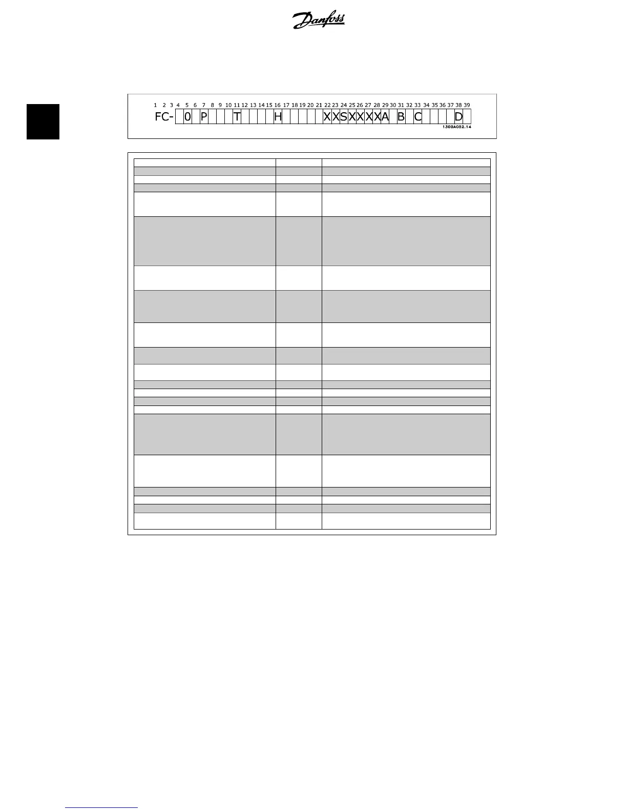
2.1.2. Type Code String
Description Pos Possible choice
Product group & VLT Series 1-6 FC 102
Power rating 8-10 1.1 - 90 kW (1K1 - 90K)
Number of phases 11 Three phases (T)
Mains voltage 11-12
T 2: 200-240 V AC
T 4: 380-480 V AC
T 6: 525-600 V AC
Enclosure 13-15
E20: IP20
E21: IP 21/NEMA Type 1
E55: IP 55/NEMA Type 12
E66: IP66
P21: IP21/NEMA Type 1 w/backplate
P55: IP55/NEMA Type 12 w/backplate
RFI filter 16-17
H1: RFI filter class A1/B
H2: Class A2
H3:RFI filter A1/B (reduced cable length)
Brake 18
X: No brake chopper included
B: Brake chopper included
T: Safe Stop
U: Safe + brake
Display 19
G: Graphical Local Control Panel (GLCP)
N: Numeric Local Control Panel (NLCP)
X: No Local Control Panel
Coating PCB 20
X. No coated PCB
C: Coated PCB
Mains option 21
X: No Mains disconnect switch
1: With Mains disconnect switch (IP55 only)
Adaptation 22 Reserved
Adaptation 23 Reserved
Software release 24-27 Actual software
Software language 28
A options 29-30
AX: No options
A0: MCA 101 Profibus DP V1
A4: MCA 104 DeviceNet
AG: MCA 108 LON works
AJ: MCA 109 BAC Net
B options 31-32
BX: No option
BK: MCB 101 General purpose I/O option
BP: MCB 105 Relay option
BO:MCB 109 Analog I/O
C0 options MCO 33-34 CX: No options
C1 options 35 X: No options
C option software 36-37 XX: Standard software
D options 38-39
DX: No option
D0: DC back-up
Table 2.1: Type code description.
The various options are described further in the
VLT® HVAC Drive Design Guide
.
2. Introduction VLT
®
HVAC Drive Operating Instructions
10
MG.11.A4.02 - 09.10.06. VLT
®
is a registered Danfoss trademark
2

 Loading...


