4.1.18. How to Test Motor and Direction of Rotation.
Note that unintended motor start can occur, ensure no personnel or equipment is
in danger!
Please follow these steps to test the motor connection and direction of rotation. Start with no
power to the unit.
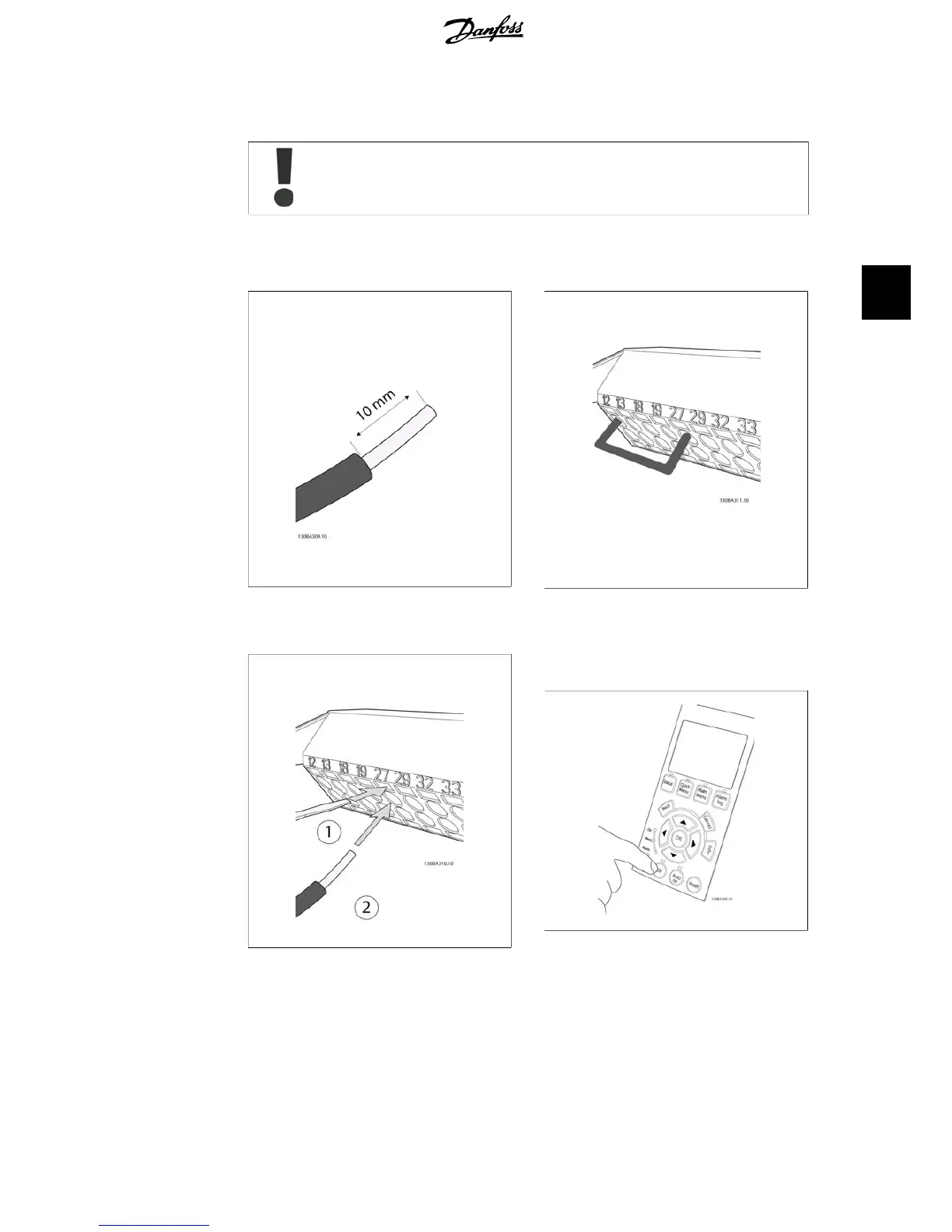
Illustration 4.19:
Step 1: First remove the insulation on both ends
of a 50 to 70 mm piece of wire.
Illustration 4.20:
Step 2: Insert one end in terminal 27 using a
suitable terminal screwdriver. (Note: For units
with Safe Stop function, the existing jumper be-
tween terminal 12 and 37 should not be removed
for the unit to be able to run!)
Illustration 4.21:
Step 3: Insert the other end in terminal 12 or 13.
(Note: For units with Safe Stop function, the ex-
isting jumper between terminal 12 and 37 should
not be removed for the unit to be able to run!)
Illustration 4.22:
Step 4: Power-up the unit and press the [Off]
button. In this state the motor should not rotate.
Press [Off] to stop the motor at any time. Note the
LED at the [OFF] button should be lit. If alarms or
warnings are flashing, please see chapter 7 re-
garding these.
VLT
®
HVAC Drive Operating Instructions 4. Electrical installation
MG.11.A4.02 - 09.10.06. VLT
®
is a registered Danfoss trademark
35
4

 Loading...


