130BE201.11
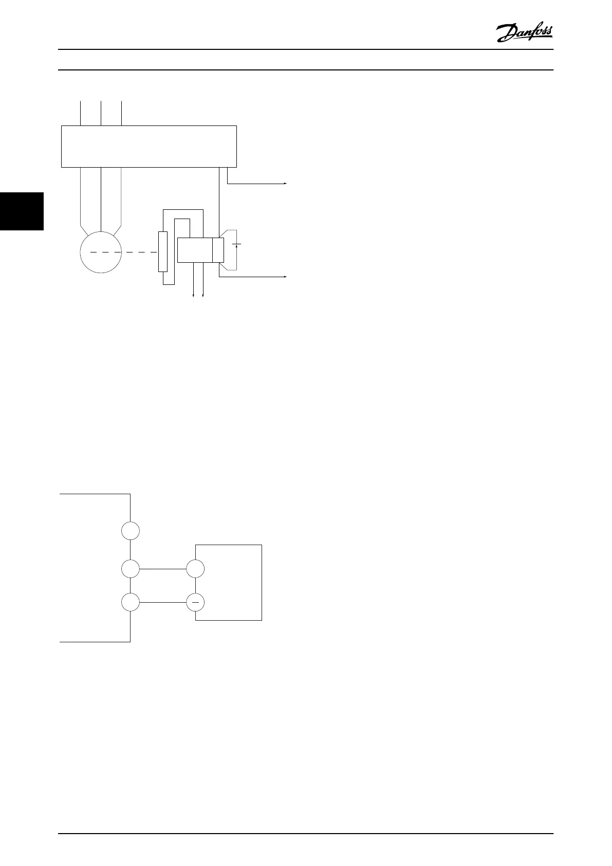
L1(N) L2(L) L3
U V W
02 01
A1
A2
Frequency converter
Output
relay
Command circuit
220 V AC
Mechanical
brake
ShaftMotor
Freewheeling
diode
Brake power circuit
380 V AC
Output
contactor
input
Illustration 4.10 Connecting the Mechanical Brake to the
Frequency Converter
4.8.5 RS485 Serial Communication
Connect RS485 serial communication wiring to terminals
(+)68 and (-)69.
•
Screened serial communication cable is
recommended.
•
See chapter 4.3 Grounding for proper grounding.
61
68
69
+
130BB489.10
RS-485
Illustration 4.11 Serial Communication Wiring Diagram
For basic serial communication set-up, select the following:
1. Protocol type in parameter 8-30 Protocol.
2. Frequency converter address in
parameter 8-31 Address.
3. Baud rate in parameter 8-32 Baud Rate.
•
Two communication protocols are internal to the
frequency converter. Follow motor manufacturer
wiring requirements.
- Danfoss FC
- Modbus RTU
•
Functions can be programmed remotely using
the protocol software and RS485 connection, or
in parameter group 8-** Communications and
Options .
•
Selecting a specic communication protocol
changes various default parameter settings to
match the specications of the protocol, and
makes extra protocol-specic parameters
available.
Electrical Installation
VLT
®
Midi Drive FC 280
18 Danfoss A/S © 11/2015 All rights reserved. MG07A102
44
 Loading...


