6.1 Safety Precautions for STO
Qualied personnel
Only qualied personnel are allowed to install or operate
this equipment.
Qualied personnel are dened as trained sta, who are
authorized to install, commission, and maintain equipment,
systems, and circuits in accordance with pertinent laws and
regulations. Additionally, the personnel must be familiar
with the instructions and safety measures described in this
manual.
NOTICE
After installation of STO, perform a commissioning test
as specied in chapter 6.3.3 STO Commissioning Test. A
passed commissioning test is mandatory after rst instal-
lation and after each change to the safety installation.
WARNING
RISK OF ELECTRICAL SHOCK
The STO function does NOT isolate mains voltage to the
frequency converter or auxiliary circuits, and therefore
does not provide electrical safety. Failure to isolate the
mains voltage supply from the unit and wait the time
specied could result in death or serious injury.
•
Perform work on electrical parts of the
frequency converter or the motor only after
isolating the mains voltage supply and waiting
the time specied in chapter 2.3.1 Discharge
Time.
NOTICE
When designing the machine application, consider the
timing and distance for a coast to stop (STO). For more
information regarding stop categories, refer to EN
60204-1.
6.2 Safe Torque O Installation
For motor connection, AC mains connection, and control
wiring, follow the instructions for safe installation in
chapter 4 Electrical Installation.
Enable the integrated STO as follows:
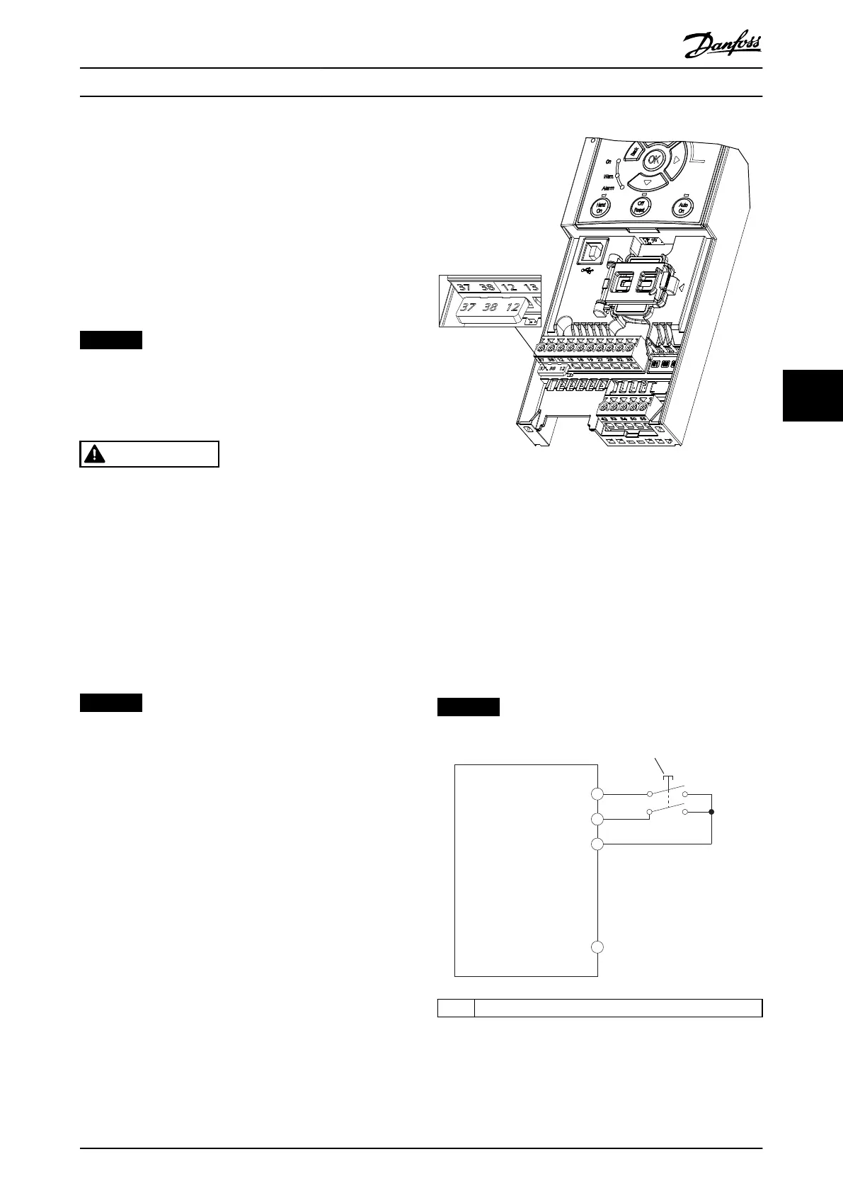
1. Remove the jumper between control terminals 12
(24 V), 37, and 38. Cutting or breaking the jumper
is not sucient to avoid short-circuiting. See the
jumper in Illustration 6.3.
Illustration 6.3 Jumper between Terminal 12 (24 V), 37, and 38
2. Connect a dual-channel safety device (for
example safety PLC, light curtain, safety relay, or
emergency stop button) to terminals 37 and 38
to form a safety application. The device must
comply with the desired safety level based on the
hazard assessment. Illustration 6.4 shows the
wiring schematic of STO applications where the
frequency converter and the safety device are in
the same cabinet. Illustration 6.5 shows the wiring
schematic of STO applications where external
supply is used.
NOTICE
The STO signal must be PELV supplied.
130BE424.10
FC 280
37
38
12
55
1
1 Safety device
Illustration 6.4 STO Wiring in 1 Cabinet, Frequency Converter
Provides the Supply Voltage
Safe Torque O (STO) Operating Instructions
MG07A102 Danfoss A/S © 11/2015 All rights reserved. 33
6
6
 Loading...


