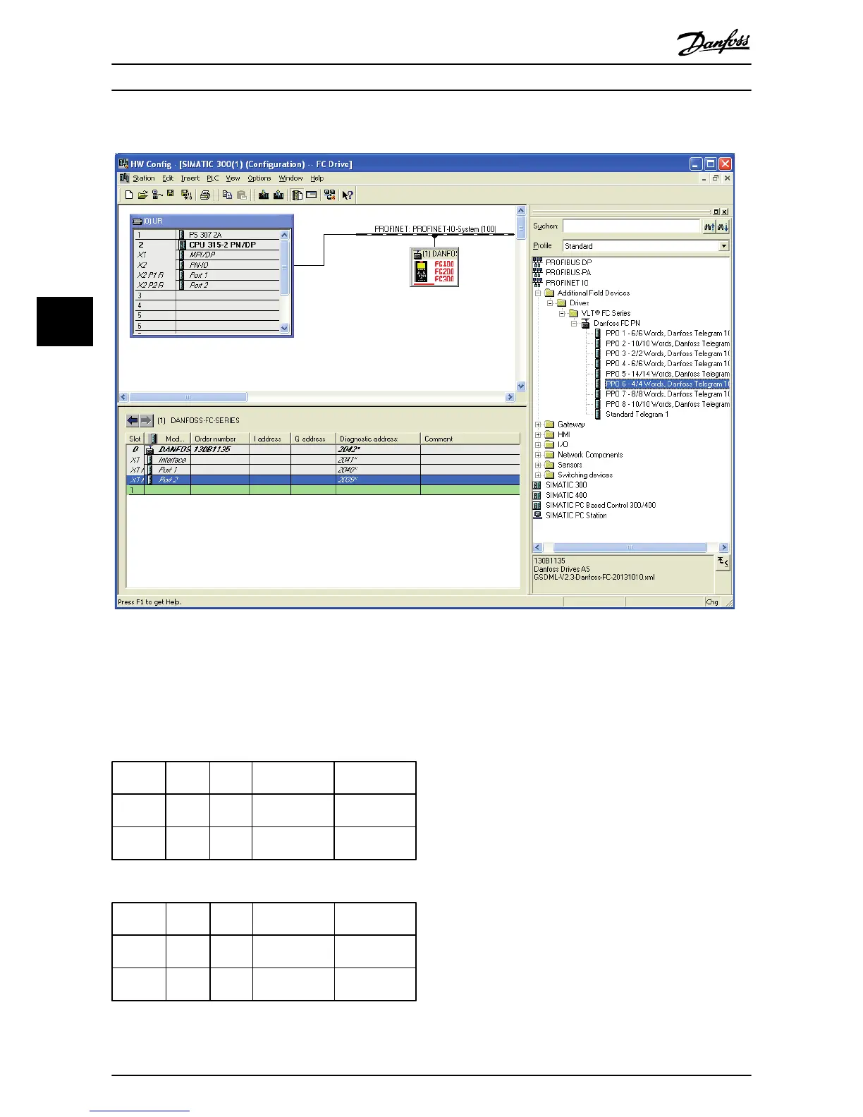
Illustration 5.5 Set up the Peripheral Input and Output Data
The configuration tool automatically assigns addresses in
the peripheral address area. In this example the input and
output area have the following configuration:
PPO type 6
PCD word
number
0 1 2 3
Input
address
256-257 258-259 260-261 262-263
Set-up STW MAV
9-16 PCD Read
Configuration.2
9-16 PCD Read
Configuration.3
Table 5.2 PCD Read (VLT to PLC)
PCD word
number
0 1 2 3
Output
address
256-257 258-259 260-261 262-263
Set-up CTW MRV
9-15 PCD Write
Configuration.2
9-15 PCD Write
Configuration.3
Table 5.3 PCD Write (PLC to VLT)
Assign the PCDs via
9-16 PCD Read Configuration for inputs
and 9-15 PCD Write Configuration for outputs.
Download the configuration file to the PLC. The PROFINET
system should start data exchange when the PLC is set to
Run mode.
How to Configure the System Operating Instructions
22 Danfoss A/S © Rev. 2014-02-27 All rights reserved. MG90U302
55
 Loading...


