39
MG.10.J8.02 – VLT is a registered Danfoss trade mark
Programmable SyncPos motion controller
■■
■■
■ Quick Start Tutorial for impatient users
1. Start → "CAM-EDITOR" and load VLT
parameters as cnf file into the CAM-Editor:
"FILE" → "LOAD CNF".
2. Enter gearing factors or set user units MU and
UU.
3. Enter at least three → "FIX POINTS" for
master and slave in the index card with the
same name.
4. Enter → "START STOP POINTS" for the
engaging and disengaging.
5. Define the → "NUMBER OF INTERVALS" for
a master cycle length in the index card
"CURVE DATA".
The → "INTERVAL TIME" in the index card
"CURVE INFO" should not be less than 20 ms.
6. Define the → "SLAVE STOP POSITION" in the
index card "CURVE INFO".
7. Enter the number of → "CYCLES/MIN
MASTER" in the index card "CURVE INFO".
8. Check the velocity and acceleration of the
slave with the help of the diagram.
9. Save curve as cnf file → "SAVE CNF AS" and
load into the VLT.
CAM Control
■■
■■
■ Example: Stamping of boxes with use-by date
The following example explains step by step how
to edit the curve for this application of the CAM
control and then how to incorporate it into your
control program.
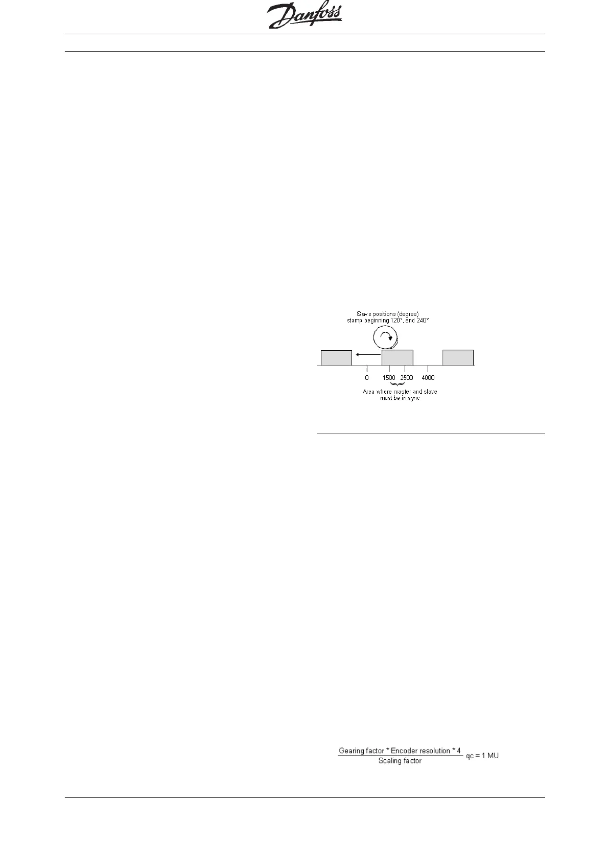
A roller is supposed to stamp an inscription with a
length of 10 cm on cardboard boxes. The stamp
corresponds to a roller section of 120 degrees.
60 cardboard boxes are transported on the con-
veyor belt per minute. The cardboard boxes are
always transported on the conveyor belt at exactly
the same distance from each other (e.g. by means
of a mechanical set pattern). During the printing
process, the stamping roller and the cardboard box
must run in sync:
How to edit the curve step by step
1. Set the VLT with the required parameters and
save these user parameters with
"PARAMETERS" → "SAVE TO FILE" with the
extension „cnf“.
2. Start the → "CAM-EDITOR" and load this cnf
file with File → "LOAD CNF".
3. Determine the gearing factor of the master in
MU units.
The input should be possible in 1/10 mm
resolution.
The drive is connected with the conveyor belt
by means of a gearing of 25:11; i.e. the motor
makes 25, the drive pulley 11 revolutions.
Gearing factor = 25/11
Incremental encoder directly on the master
drive; encoder resolution = 4096.
The drive pulley has 20 teeth/revolution,
2 teeth correspond to 10 mm, thus 1 revolution
corresponds to = 100 mm conveyor belt feed
or 1000/10 mm.
Thus, the scaling factor is 1000.
Stamping roller = Slave
Conveyor belt = Master
Master positions (1/100 mm)

 Loading...


