Removal and Replacement
4-5
2. Secure the Front Panel PCB to the chassis using the two Screws.
3. If servicing a display-equipped model, install the Bezel over the Front Panel PCB;
otherwise, go to Step 4.
4. Install the Front Panel; see Section 4.2.
5. If servicing a non-display model, adjust the darkness; see Section 2.7.
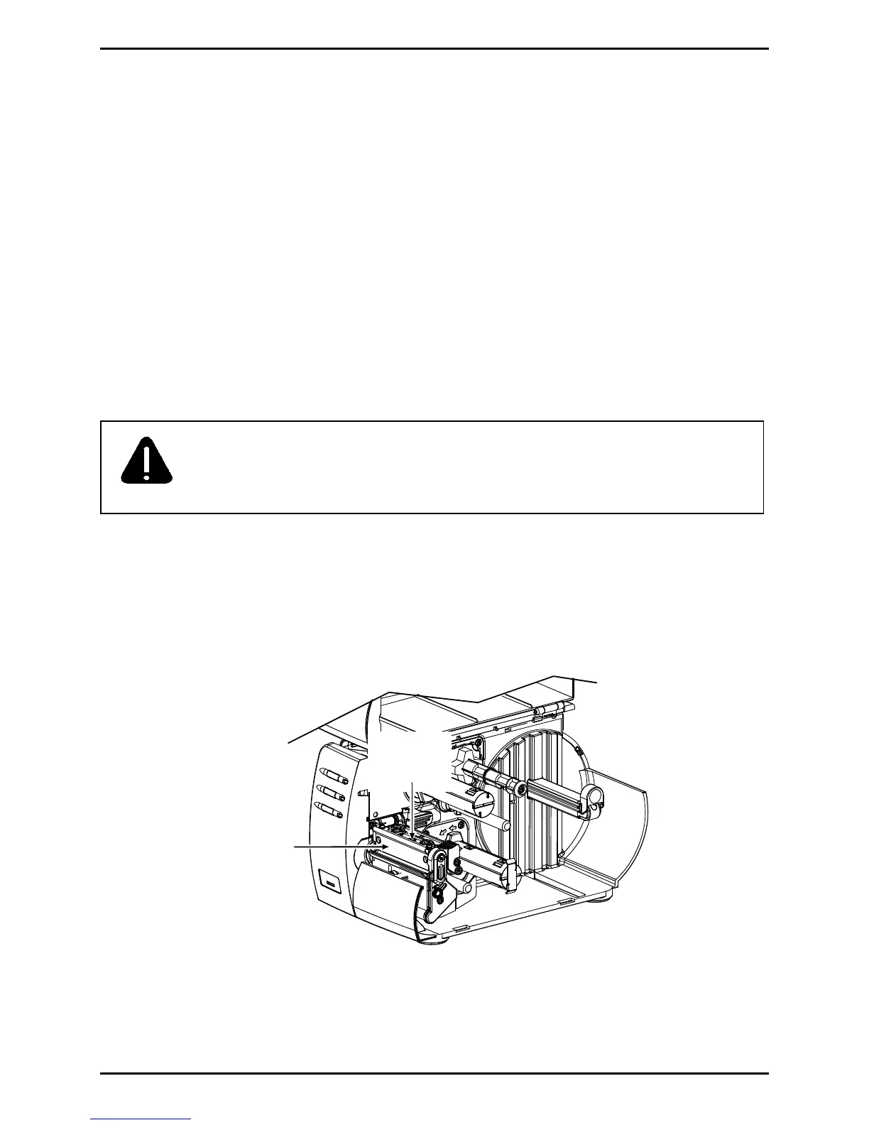
4.3 Printhead
CAUTION
If over-voltage is suspected, see Section 2.10.
Handle the printhead with extreme care and never use a sharp object on
the printhead surface.
Removal:
1. Turn OFF and unplug the printer. Open the cover; if ribbon is installed, remove it.
2. With the Printhead Assembly latched, loosen the Printhead Mounting Screw (it will
remain in the assembly).
Printhead
Assembly
Printhead
Mounting
Screw
3. Unlatch then raise the Printhead Assembly. Carefully slide the Printhead out of the
assembly (see detail, below) then disconnect the two cables and remove the Printhead.
 Loading...