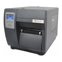
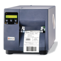
Removal and Replacement
4-17
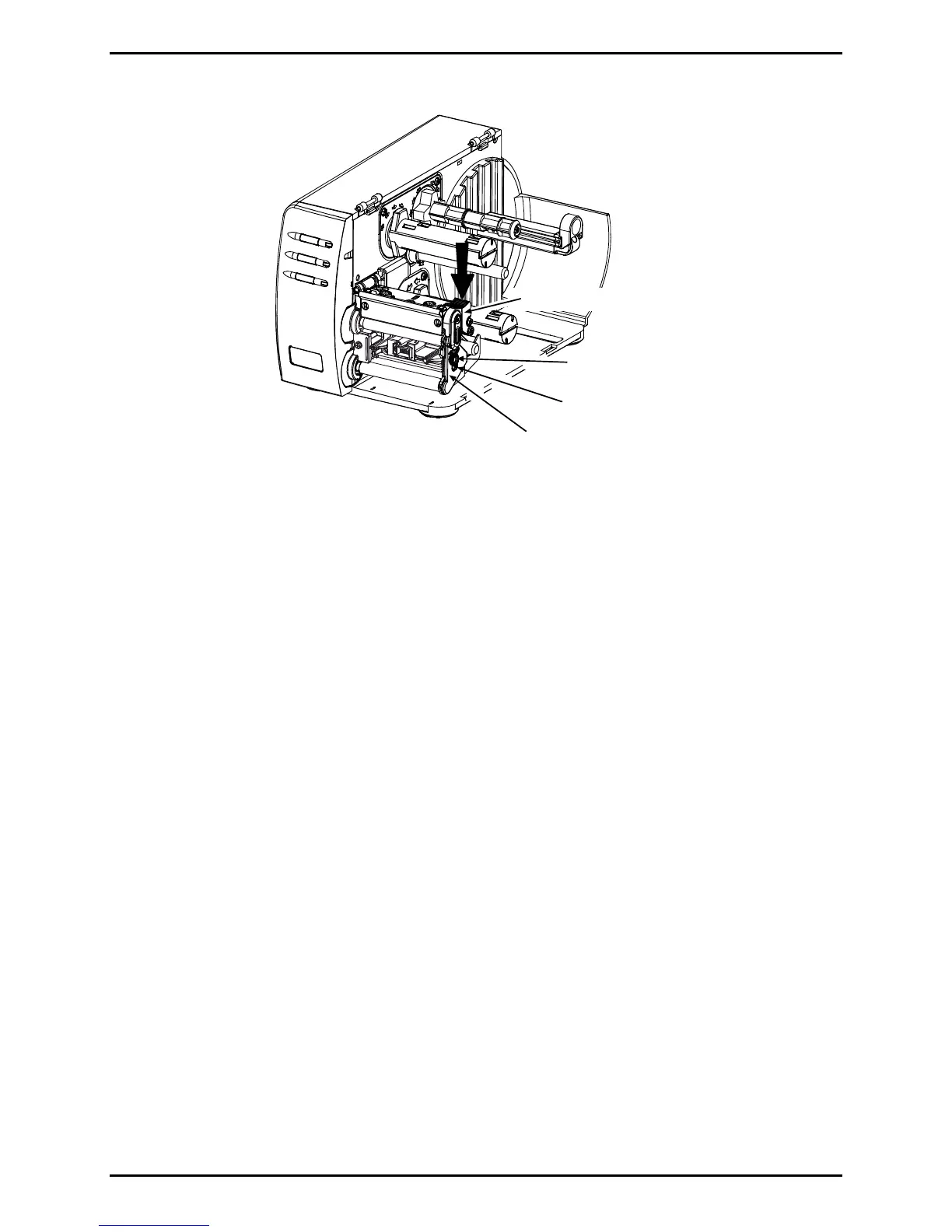
Printhead Assembly
Leveling Cam
Screw
Outer Bearing Plate
5. Connect the Media Sensor Cable to J7 on the Main Logic PCB; see Section 4.4. Press the
connector lock down and then close the Strain Relief.
6. Install the Side Cover Assembly; see Section 4.1.
7. Plug in and turn ON the printer. Perform the Media Width Adjustment; see Section 2.3.
4.7 Drive Motor
Removal:
1. Turn OFF and unplug the printer.
2. Remove the Side Cover Assembly (see Section 4.1) and the Front Cover (see Section
4.2). Also, if the printer is equipped with an Assist Roller, remove the fascia and any
output attachment (e.g., tearplate, arc plate, etc; see Section 4.8 for details).
3. Raise the Printhead Assembly and proceed according to equipped type: If equipped with
an Assist Roller, remove the Screw that secures the Inner Bearing Plate and then
remove the Inner Bearing Plate from the Platen Block; otherwise, go to Step 4.
 Loading...