2. Remove the base cover.
3. Remove the battery.
4. Remove the rear cover.
5. Remove the solid-state drive.
6. Remove the wireless card.
7. Remove the memory module.
8. Remove the system board.
NOTE: The system board can be removed as an assembly with the fan and heat-sink assembly, ethernet and audio
board, and USB board attached.
About this task
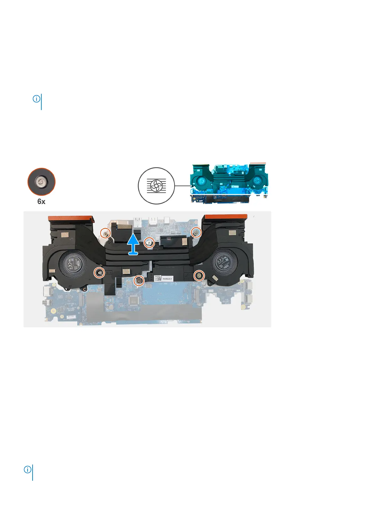
The following image indicates the location of the fan and heat-sink assembly and provides a visual representation of the removal
procedure.
Steps
1. Turn the system-board assembly over.
2. In sequential order (1>2>3>4>5>6), remove the six screws that secure the fan and heat-sink assembly to the system-board
assembly.
3. Lift the fan and heat-sink assembly off the system-board assembly.
Installing the fan and heat-sink assembly
Prerequisites
If you are replacing a component, remove the existing component before performing the installation procedure.
About this task
The following image indicates the location of the fan and heat-sink assembly and provides a visual representation of the
installation procedure.
NOTE:
If either the system board or theheat sinkis replaced, use the thermal pad that is provided in the kit to ensure that
thermal conductivity is achieved.
82 Removing and installing Field Replaceable Units (FRUs)
 Loading...