Utility Panel
The Utility panel side of the platform contains the fan and power modules.
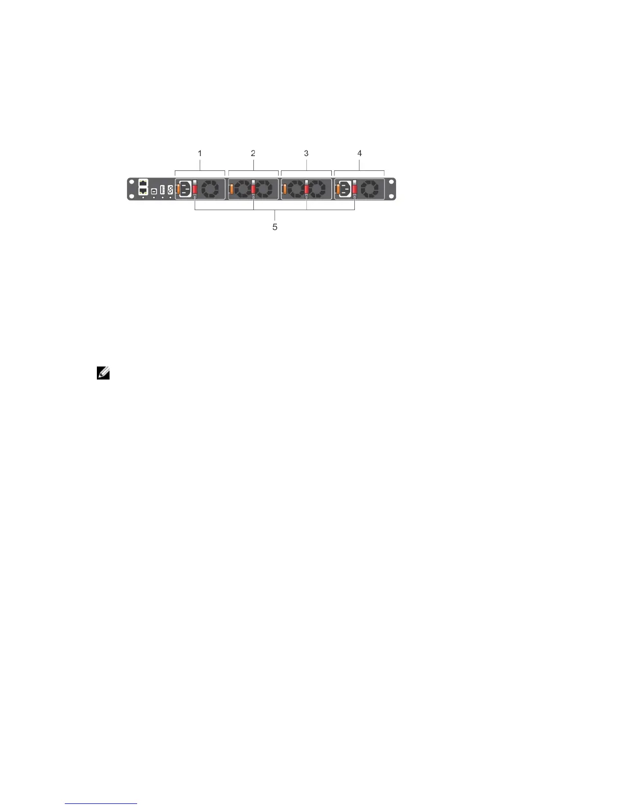
Figure 3. S5000 Power Supplies and Fan Modules
1. Slot 0 (for PSU 0)
2. Slot 1 (for Fan Module 0)
3. Slot 2 (for Fan Module 1)
4. Slot 3 (for PSU 1)
5. Grab Handles
Power Supplies
The S5000 supports two hot-swappable PSUs.
NOTE: The PSUs must be installed at the customer site.
The S5000 has SKUs that support the following configurations:
• AC PSU with fan airflow from I/O to Utility
• AC-R PSU with fan airflow from Utility to I/O
• DC PSU with fan airflow from I/O to Utility
• DC-R PSU with fan airflow from Utility to I/O
PSUs are field replaceable. To ensure power redundancy and adequate cooling, install two power supplies in the
switch. When running with full redundancy (two PSUs installed and running), you can remove and replace one PSU
while the other PSU is running without disrupting traffic.
Fans
The S5000 supports two fan trays with airflow directions from I/O to Utility or Utility to I/O.
Do not mix I/O to Utility and Utility to I/O airflows in a single S5000 chassis. All fans and PSUs in a configuration must be
in the same airflow direction. If you create a mixed airflow configuration, the software notifies you of the invalid
configuration.
The fans must be installed at the customer site.
12
 Loading...