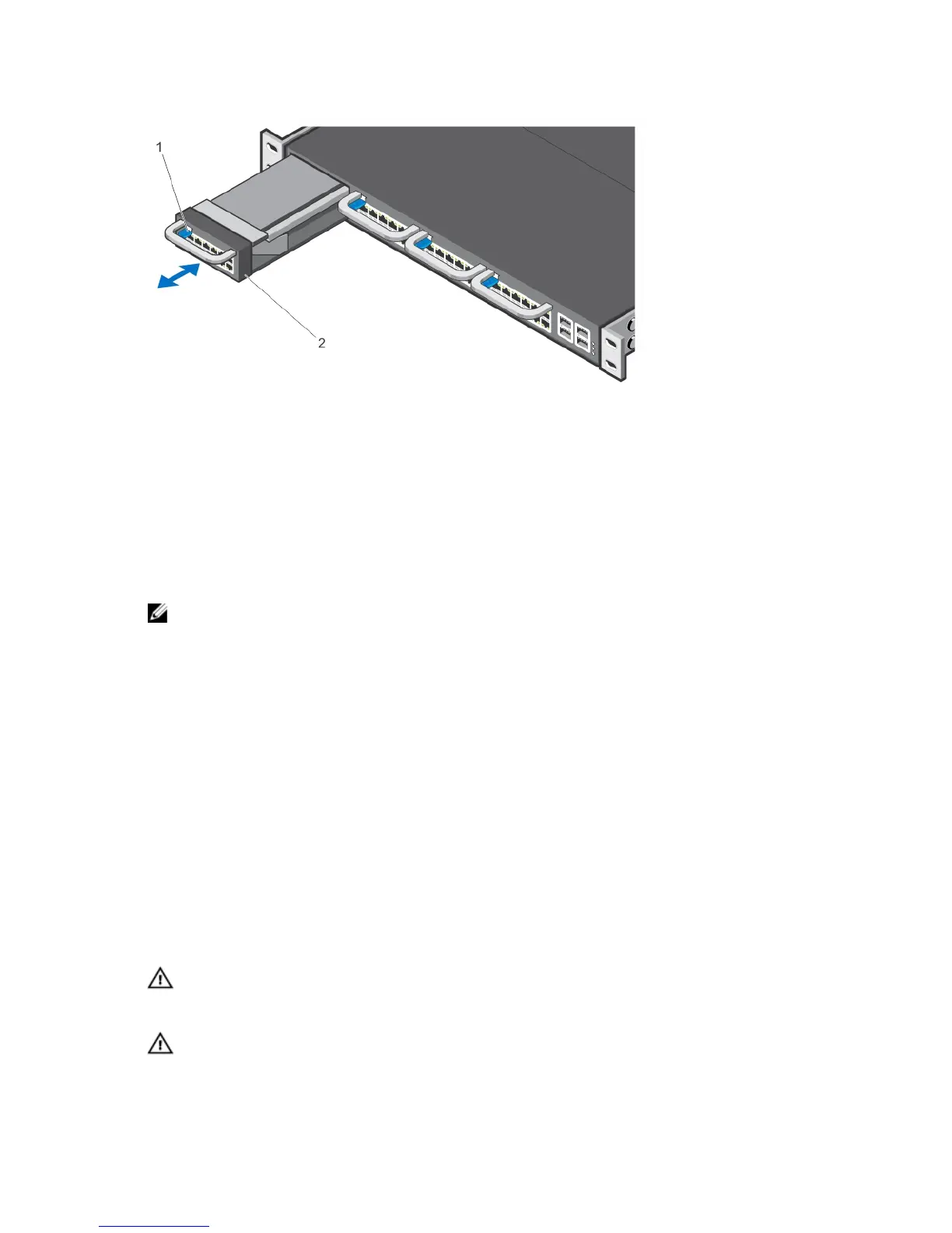
Figure 14. Installing a Fibre Channel Module
1. Release latch
2. Fibre Channel Module
Replacing a Fibre-Channel Module
NOTE: S5000 does not support the hot swapping of a Fibre-Channel pluggable module during switch operations.
Instead, you must power down the switch before removing and replacing an expansion module.
1. Disconnect any network interface cables attached to the module.
2. Use the grab handle to slide the Fibre-Channel module out of the switch module slot.
3. Use the grab handle on the replacement Fibre-Channel module to slide it into the switch module slot.
4. Connect any network interface cables to the attached module.
Important Points to Remember for Installing an AC Power Supply
• The PSU slides into the slot smoothly. Do not force a PSU into a slot as this action may damage the PSU or the
S5000 chassis.
• The S5000 supports AC and DC power supplies with two air-flow directions (I/O to Utility and Utility to I/O). The
S5000 does not support mixing PSU types, that is, you cannot replace an AC PSU with a DC PSU and an AC-R
PSU with a DC-R PSU. The fan airflow direction for both the PSUs must be the same.
• For AC PSUs, an illuminated translucent handle indicates the power status.
• To view the log messages, use the show logging command. For more information, refer to the System Logs
chapters of the
FTOS Command Line Reference Guide for the S5000 Switch
and
FTOS Configuration Guide for the
S5000 Switch
.
WARNING: Although the switch can run on one PSU, Dell Networking highly recommends using two PSUs for full
redundancy and proper cooling. If the switch needs to run with only one PSU for a time, be sure to cover the
second PSU slot opening with a blank plate to avoid overheating.
WARNING: The Utility panel consists of four slots numbered from 0 to 3. Insert PSUs in slots 0 and 3.
28
 Loading...