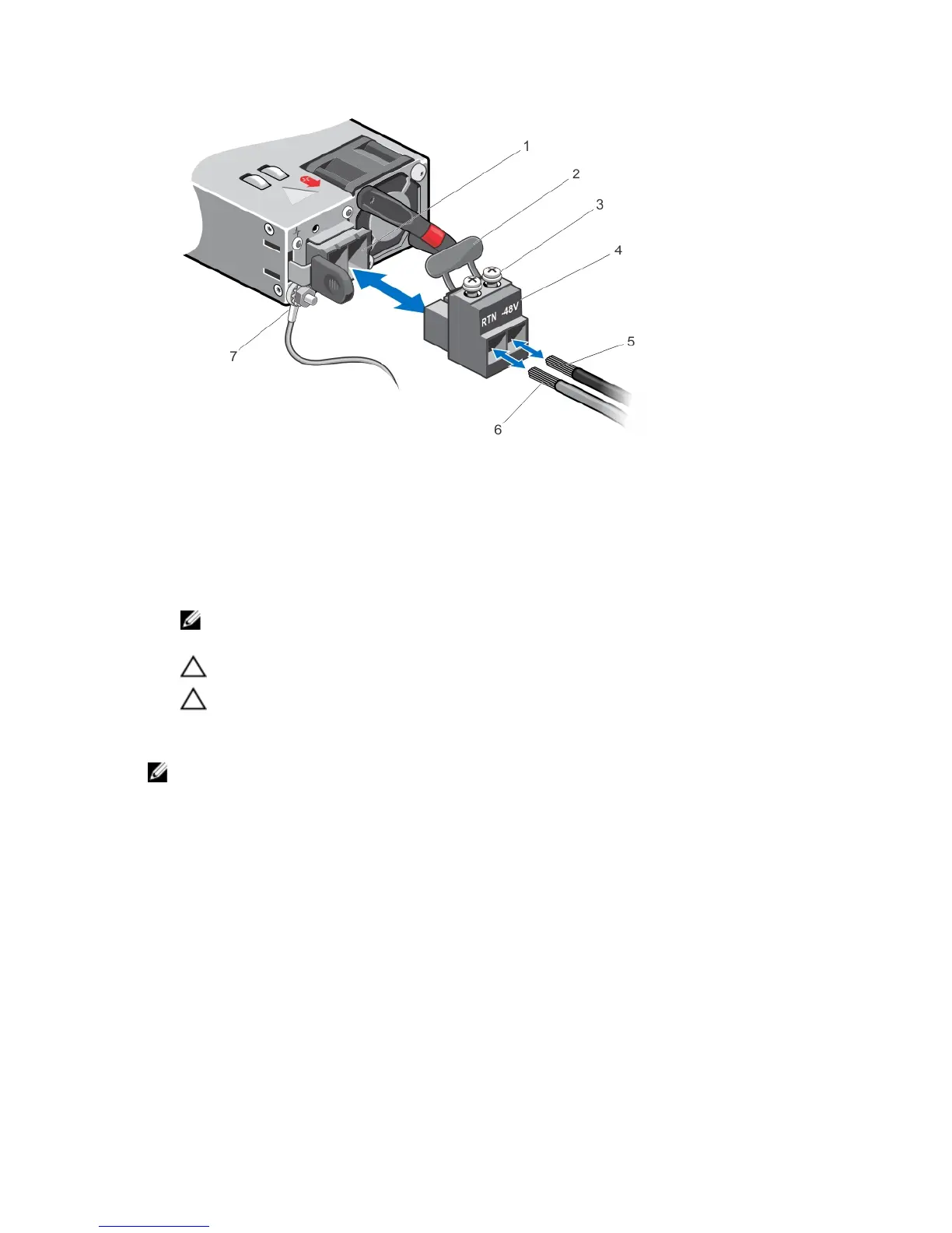
Figure 19. Assembling the DC Input Power Wires
1. DC power socket
2. Rubber cap
3. Captive screws (2)
4. DC power connector
5. Wire (-48V)
6. Wire RTN
7. Grounding Wire
NOTE: The system is powered-up as soon as the power cord is connected between the system and the power
source.
CAUTION: Always disconnect the power cable before you service the power supply slots.
CAUTION: Use the power supply cord as the main disconnect device on the AC or DC system. Ensure that the
socket-outlet is located/installed near the equipment and is easily accessible.
7. Repeat steps 1 through 6 using the second PSU.
NOTE: Ensure that the PSU is correctly installed. When you correctly install the PSU, the power connector is on the
left side of the PSU.
Installing the Ferrite Bead for DC Power and Return Cables
Add a ferrite bead to the DC power and return cables of the master module. Install the bead with a single loop.
1. Open ferrite bead with the depressions facing up.
2. Wrap the DC power and return cables around the ferrite bead twice if two turns of the cable fit inside the ferrite,
otherwise simply clamp the ferrite onto both cables.
34
 Loading...