8. Remove the display assembly.
9. Remove the speakers.
10. Remove the system board.
11. Remove the I/O daughterboard.
12. Remove the power button.
13. Remove the keyboard.
NOTE: When removing the system board to replace or access other parts, the system board can be removed and
installed with the heat sink attached to simplify the procedure and preserve the thermal bond between the system board
and heat sink.
About this task
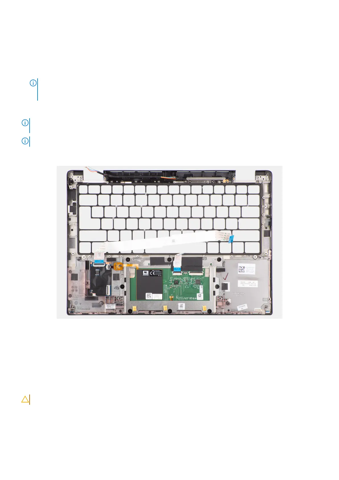
NOTE: The palm-rest assembly cannot be further disassembled once all the pre-removal parts procedures are completed. If
the keyboard is malfunctioning and is required to be replaced, replace the entire palm-rest assembly.
NOTE: The smart card reader is a replaceable component for the models with security configurations.
The image below shows the palm-rest assembly after the pre-removal parts procedures have been performed for any palm-rest
assembly replacement.
Figure 84. Removing the palm-rest assembly
Steps
1. For computers shipped with a carbon fiber palm-rest, use a fine-tipped instrument to push the nanoSIM outwards to remove
it from its slot on the palm-rest assembly.
2. After performing the pre-requisites, you are left with the palm-rest assembly.
Installing the palm-rest assembly
CAUTION: The information in this installation section is intended for authorized service technicians only.
Prerequisites
If you are replacing a component, remove the existing component before performing the installation procedure.
112
Removing and installing Field Replaceable Units (FRUs)
 Loading...