Prerequisites
If you are replacing a component, remove the existing component before performing the installation procedure.
About this task
NOTE: If either the system board or the heat-sink is replaced, use the thermal grease that is provided in the kit to ensure
that thermal conductivity is achieved.
NOTE: Incorrect alignment of the heat-sink can damage the system board and processor.
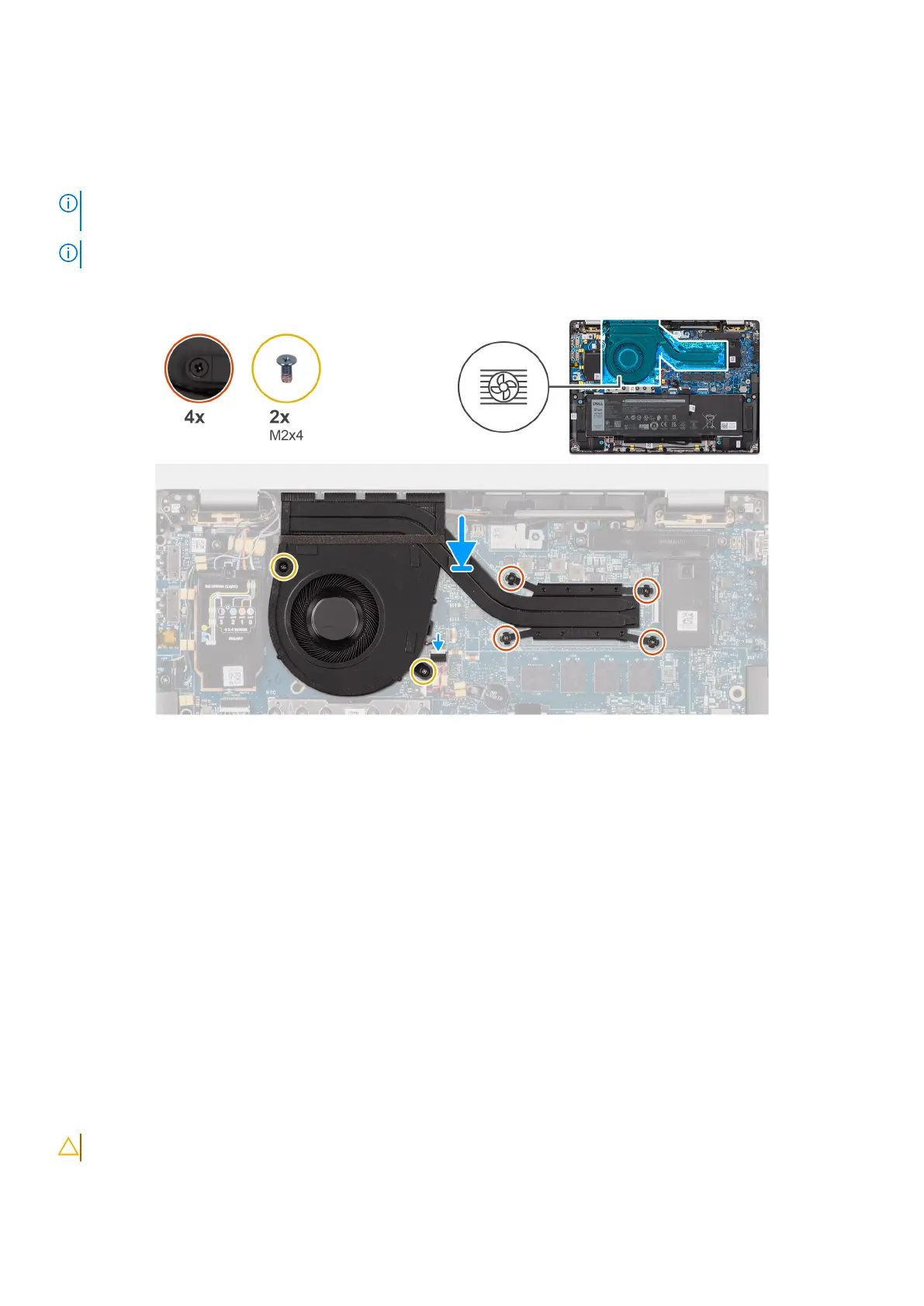
The following image indicates the location of the heat-sink and provides a visual representation of the installation procedure.
Figure 47. Installing the heat-sink and fan assembly
Steps
1. Place the heat-sink on the system board.
2. Align the screw holes on the heat-sink and fan assembly with the screw holes on the system board.
3. Replace the four captive screws and two screws (M2x4) that secure the system fan to the system board.
4. In reverse sequential order (as indicated on the heat-sink), tighten the four captive screws that secure the heat-sink and fan
assembly to the system board.
5. Connect the computer fan cable to the connector on the system board.
Next steps
1. Install the base cover.
2. Follow the procedure in After working inside your computer.
Display assembly
Removing the display assembly
CAUTION: The information in this removal section is intended for authorized service technicians only.
Removing and installing Field Replaceable Units (FRUs) 77
 Loading...