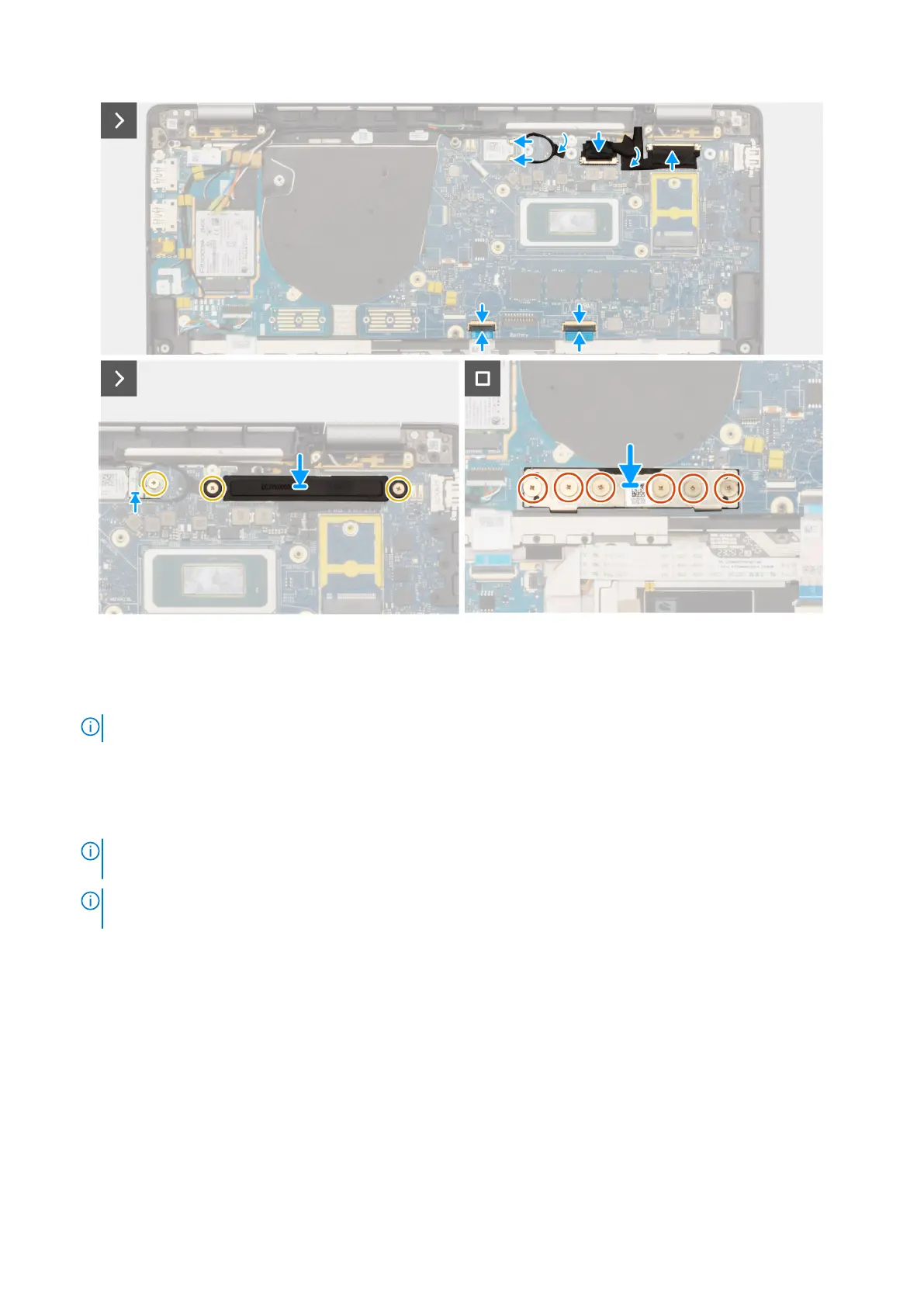
Figure 65. Installing the system board
Steps
1. Place the system board into the respective slot on the palm-rest and keyboard assembly.
NOTE: Transfer the reusable WLAN absorbers to the new system board while replacing the system board.
2. Replace the two screws (M2.2x5) and three screws (M2x4) securing the system board in place.
3. Connect the (1) camera cable, (2) display cable, (3) Click pad flexible flat cable, and (4) USH daughterboard flexible flat
cable (for models shipped with a USH daughterboard) on the system board.
4. Replace the I/O daughterboard bridge connector board on the computer.
NOTE:
When reinstalling the I/O daughterboard bridge connector board align the connector so that the arrows etched
on the connector are pointed upward towards the heat-sink and fan assembly.
NOTE: When reinstalling the I/O daughterboard bridge connector board secure the six screws (M2x4) in sequential
order (1 > 2 > 3 > 4 > 5 > 6) marked on the FPC.
5. Replace the six screws (M2x4) securing the I/O daughterboard bridge connector board in place.
6. Align and place the display cable bracket on the computer.
7. Replace the two screws (M2x2) securing the display cable bracket on the system board.
8. Connect the WLAN Main and Aux antenna to the WLAN module.
9. Replace the WLAN module bracket on the computer.
10. Replace the single screw (M2x2) screw securing the WLAN module bracket in place.
Next steps
1. Install the heat-sink.
2. Install the 2-cell battery or the 3-cell battery, whichever is applicable.
3. Install the M.2 2230 solid-state drive.
4. Install the base cover.
Removing and installing Field Replaceable Units (FRUs)
93
 Loading...