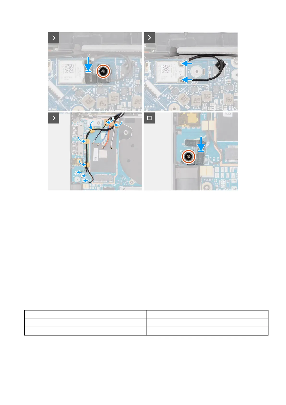
Figure 69. Installing the WLAN-antenna module
Steps
1. Slide and replace the WLAN-antenna module to the WLAN-antenna module slot on the system board.
2. Route the WLAN-antenna cables from the routing guides on the system board.
3. Replace the four screws (M1.6x2.5) that secure the WLAN-antenna module bracket on the system board.
4. Peel back the pieces of tape securing the black WLAN Aux antenna cable on the system board.
5. Connect the antenna cables to the connectors.
6. Slide and place the 5G WWAN card from the WWAN card slot on the system board.
7. Connect the two Darwin antenna cables, and green P-sensor cable from the routing guide on the I/O daughterboard.
8. Align and place the 5G WWAN card bracket on the system board.
9. Replace the single screw (M2x2.5) that secure the 5G WWAN shielding cover on the system board.
10. Replace the 5G WWAN shielding cover on the system board.
11. Align and place the Darwin antenna cable bracket on the system board.
12. For computers shipped with WWAN antennas, replace the single screw (M2x2) that secure the Darwin antenna cable
bracket on the system board.
Table 31.
WLAN-antenna cable color scheme
Connectors on the wireless card Antenna cable color
Main (white triangle) White
Auxiliary (black triangle) Black
Next steps
1. Install the 2-cell battery or the 3-cell battery, whichever is applicable.
2. Install the heat sink.
98
Removing and installing Field Replaceable Units (FRUs)