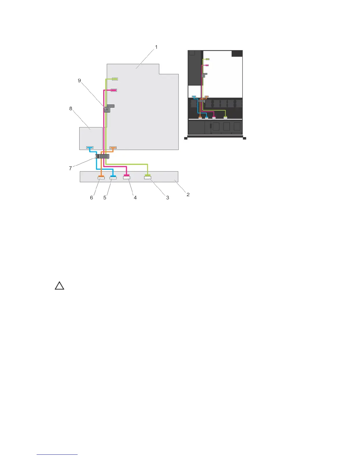
Figure 51. Cabling Diagram—Eight Hard-Drive Backplane
1. system board
2. hard-drive backplane
3. SAS B cable connector
4. SAS A cable connector
5. power cable connector
6. signal cable connector
7. cable routing latch
8. power distribution board
9. cable retention latch
Installing The Hard-Drive Backplane
CAUTION: Many repairs may only be done by a certified service technician. You should only perform
troubleshooting and simple repairs as authorized in your product documentation, or as directed by the online or
telephone service and support team. Damage due to servicing that is not authorized by Dell is not covered by your
warranty. Read and follow the safety instructions that came with the product.
1. Use the hooks at the base of the chassis as guides to align the hard-drive backplane.
2. Slide down the hard-drive backplane until the release tabs snap into place.
3. Connect the SAS/SATA/SSD data, signal, and power cable(s) to the backplane.
4. Install the hard drives in their original locations.
5. Close the system.
6. Reconnect the system to its electrical outlet and turn the system on, including any attached peripherals.
7. If applicable, install the front bezel.
Control Panel Assembly
90
 Loading...