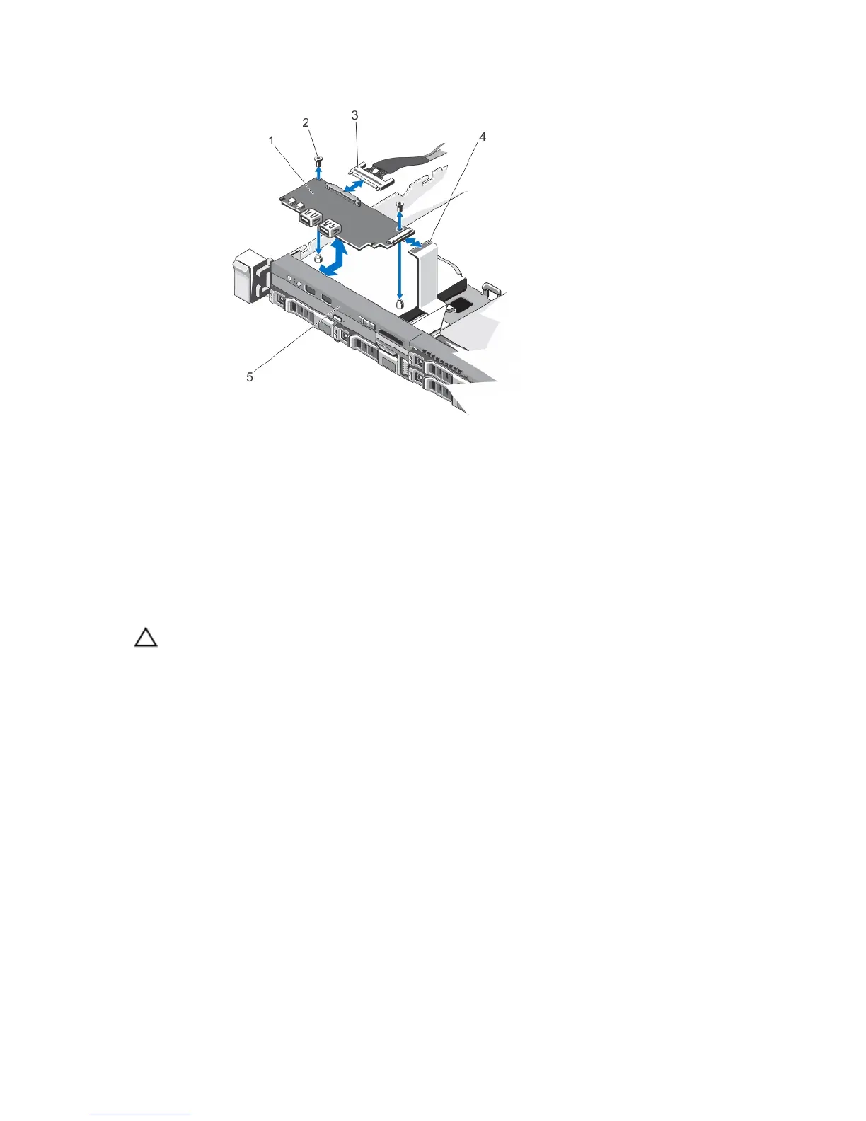
Figure 56. Removing and Installing the Control-Panel Module—2.5 Inch Hard Drive System
1. control-panel module
2. screws (2)
3. control-panel module connector cable
4. LCD connector cable
5. control panel
Installing The Control-Panel Module
CAUTION: Many repairs may only be done by a certified service technician. You should only perform
troubleshooting and simple repairs as authorized in your product documentation, or as directed by the online or
telephone service and support team. Damage due to servicing that is not authorized by Dell is not covered by your
warranty. Read and follow the safety instructions that came with the product.
1. For a 3.5 inch cabled hard drive system:
a) Insert the LED panel into the slot in the chassis.
b) Secure the LED panel with the screws.
2. Insert the control-panel module into the slot in the chassis and align the two screw holes on the control-panel
module with the corresponding holes on the chassis.
3. Secure the control-panel module with the screws.
4. Connect all the applicable cables to the control-panel module.
5. Close the system.
6. Install the control panel.
7. Reconnect the system and peripherals to their power sources, and turn them on.
8. If applicable, install the front bezel.
96
 Loading...