 Loading...
Do you have a question about the Dell PowerEdge T110 and is the answer not in the manual?
| Tcase | 72.7 °C |
|---|---|
| Bus type | DMI |
| Stepping | B1 |
| FSB Parity | No |
| Processor code | SLBLD |
| Processor cache | 8 MB |
| Processor cores | 4 |
| Processor model | X3450 |
| System bus rate | 2.5 GT/s |
| Processor series | Intel Xeon 3400 Series |
| Processor socket | LGA 1156 (Socket H) |
| Processor threads | 8 |
| Processor codename | Lynnfield |
| Processing Die size | 296 mm² |
| Processor frequency | 2.66 GHz |
| Processor cache type | Smart Cache |
| Processor lithography | 45 nm |
| Processor manufacturer | Intel |
| Processor package size | 37.5 x 37.5 mm |
| Processor front side bus | - MHz |
| Processor boost frequency | 3.2 GHz |
| Processor operating modes | 64-bit |
| ECC supported by processor | Yes |
| PCI Express configurations | 1x16, 2x8, 4x4 |
| Supported instruction sets | SSE4.2 |
| Thermal Design Power (TDP) | 95 W |
| Number of processors installed | 1 |
| CPU multiplier (bus/core ratio) | 20 |
| Maximum number of PCI Express lanes | 16 |
| Memory types supported by processor | DDR3-SDRAM |
| Number of Processing Die Transistors | 774 M |
| Memory channels supported by processor | Dual |
| Memory clock speeds supported by processor | 800, 1066, 1333 MHz |
| Memory bandwidth supported by processor (max) | 21 GB/s |
| Maximum internal memory supported by processor | 32 GB |
| HDD size | 3.5 \ |
| Hot-swap | - |
| HDD capacity | 500 GB |
| HDD interface | Serial ATA |
| Optical drive type | DVD-ROM |
| Total storage capacity | 1000 GB |
| Maximum storage capacity | - TB |
| Number of HDDs installed | 2 |
| Internal memory | 4 GB |
| Memory clock speed | 1066 MHz |
| Maximum internal memory | 16 GB |
| Memory layout (slots x size) | 2 x 2 GB |
| Graphics card | G200eW |
| USB 2.0 ports quantity | USB 2.0 ports have a data transmission speed of 480 Mbps, and are backwards compatible with USB 1.1 ports. You can connect all kinds of peripheral devices to them. |
| PCI Express slots version | 2.0 |
| Power supply | 305 W |
| Compatible operating systems | Microsoft SQL Server 2008 R2, Microsoft Windows Small Business Server 2008, Microsoft Windows Essential Business Server 2008, Microsoft Windows Server 2008 Foundation R2, Microsoft Windows Server 2008 SP2, x86/x64 (x64 Hyper-VTM), Microsoft Windows Server 2008 R2, x64 (Hyper-VTM v2), Microsoft Windows HPC Server 2008, Novell SUSE Linux Enterprise Server, Red Hat Enterprise Linux |
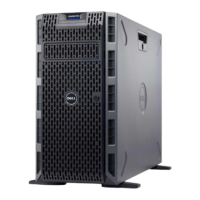
| Chassis type | Tower |
| Processor ARK ID | 42929 |
| Intel® Turbo Boost Technology | 1.0 |
| Depth | 463.8 mm |
|---|---|
| Width | 188.64 mm |
| Height | 418.55 mm |
Details keystrokes for accessing system features during startup.
Describes the front panel components and their associated indicators.
Describes the back panel components and their associated indicators.
Provides instructions for connecting external devices to the system.
Explains the meaning of different Network Interface Card (NIC) link and activity indicators.
Instructions for setting the voltage selection switch on the power supply.
Lists diagnostic indicator codes, their causes, and corrective actions.
Explains system messages displayed to notify of potential problems.
Alerts to potential problems and prompts for user response.
Messages issued when running system diagnostic tests.
Messages from management software indicating status, warning, or failure.
Points to additional documentation and safety information resources.
Explains how to select the boot mode (BIOS or UEFI) for OS installation.
Step-by-step guide to entering the system's BIOS setup utility.
Overview of the main categories of configuration options in System Setup.
Instructions for accessing the Unified Extensible Firmware Interface Boot Manager.
Overview of system and setup password security features.
Introduction to the Unified Server Configurator (USC) utility.
Details Baseboard Management Controller (BMC) features for remote management.
Lists the tools required for performing component installation procedures.
Provides an overview of the internal components of the system.
Step-by-step instructions for opening and closing the system's chassis.
Information on removing and installing the front bezel assembly.
Explanation of the purpose and removal/installation of EMI filler panels.
Details on installing optical and tape backup drives in the system's drive bays.
Information and procedures for installing and removing hard drives.
Instructions for removing and installing the expansion card stabilizer.
Information regarding the cooling shroud's function and handling procedures.
Guidelines and procedures for installing PCIe expansion cards.
Information about system memory modules (DIMMs) and installation.
Instructions for installing and removing the system's processor.
Details on the system's cooling fan and its replacement.
Information and instructions for replacing the system battery.
Procedures for removing and installing the system's power supply unit.
Information on installing an optional internal USB memory key.
Instructions for removing and installing the chassis intrusion switch.
Procedures for removing and installing the system's control panel assembly.
Detailed steps for removing and installing the system board.
General safety precautions to follow when troubleshooting the system.
Steps to resolve issues that prevent the system from starting up.
Steps to troubleshoot problems with external device connections.
Procedures to diagnose and fix video output problems.
Steps to troubleshoot issues with USB devices connected to the system.
Steps to diagnose and fix problems with serial port devices.
Procedures to diagnose and fix Network Interface Card (NIC) issues.
Steps to take if the system has been exposed to liquid.
Procedures to follow if the system has sustained physical damage.
Steps to diagnose and fix issues related to the system's battery.
Procedures to diagnose and fix problems with the power supply unit.
Steps to diagnose and fix system overheating issues.
Procedures to diagnose and fix problems with the system's cooling fan.
Steps to diagnose and fix issues related to system memory modules.
Steps to diagnose and fix problems with an internal USB memory key.
Procedures to diagnose and fix issues with the optical drive.
Steps to diagnose and fix problems with the tape backup unit.
Procedures to diagnose and fix hard drive issues.
Steps to diagnose and fix problems with installed expansion cards.
Procedures to diagnose and fix processor-related issues.
Guide to using Dell's online diagnostic tools for system testing.
Overview of the features and capabilities of embedded system diagnostics.
Guidance on when to utilize the embedded system diagnostics.
Steps to launch and run the embedded system diagnostics utility.
Description of available testing options: Express, Extended, Custom, and Information.
How to select devices and options for custom diagnostic tests.
Method for choosing devices and components to be tested.
How to select specific test types for diagnostic runs.
How to view test results, errors, configuration, and parameters.
Information on system board jumper settings and their functions.
Diagram and list of system board connectors for various components.
Procedure to disable forgotten system or setup passwords using a jumper.
Information on how to contact Dell technical support and customer service.