CTA USER MANUAL
2007-05-09 - 12 - © DELTA ELECTRONICS, INC. ALL RIGHTS RESERVED
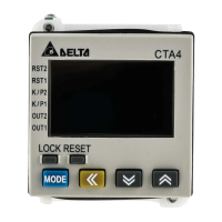
Power signal
Start signal
Pause signal
Clear signal
Power signal
Start signal
Pause signal
Clear signal
timer output not set as 0
Repeat Cycle (RCY)
Output in cycle.
When the output time is selected as 0 (left: continuous output), the output of the first timing cycle will
not be executed. When the set time is reached, the timing will be reset and restarted and the output will
be enabled until the next cycle.
When the output time is not 0 (right), the output time will be different from when the output time is 0.
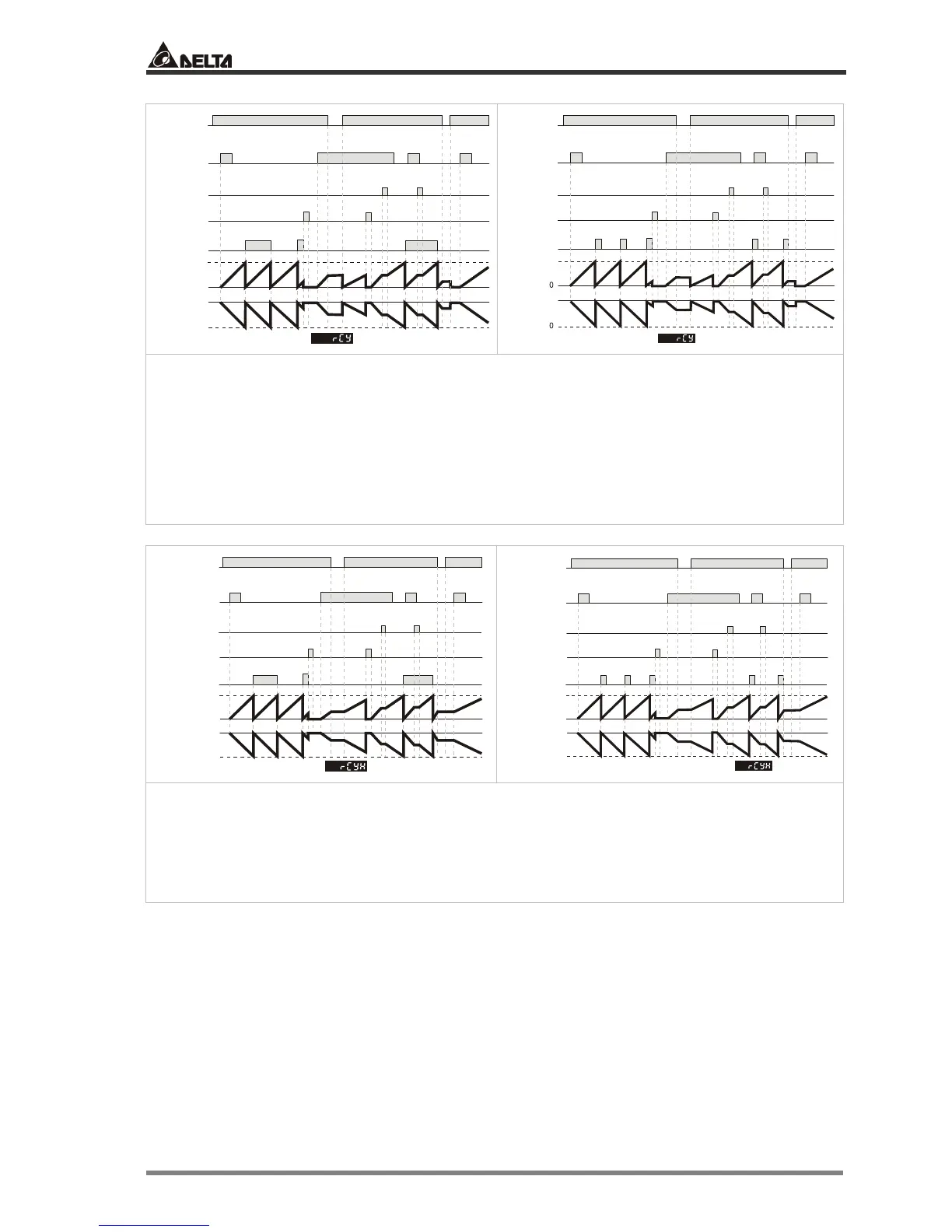
Power signal
Start signal
Pause signal
Clear signal
Power signal
Start signal
Pause signal
Clear signal
Up
Down
SV
SV
0
0
RCYH timer output not set as 0
tt
t
Repeat Cycle Hold (RCYH)
Same as “RCY”
The only difference is whether the current value is held when the power is switched off. In RCYH, After
the power is switched on, the timer will resume the timing.
 Loading...