CTA USER MANUAL
© DELTA ELECTRONICS, INC. ALL RIGHTS RESERVED - 5 - 2007-05-09
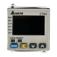
1.4 Display, Indicators & Keys
Reset 2 indicator
Reset 1 indicator
Key protect 2 indicator
Output 2 indicator
Key protect 1 indicator
Output 1 indicator
Special function indicator
Lock key
Reset key
Mode and number shift key
PV(Present Value) display
SV(Set Value) display
Timer function indicator
Counter function indicator
Up/Down key
PV: Red LCD
SV and other display areas: Green LCD
H M S: Time unit for the timer
TOTAL: Total counting value
BATCH: Batch counting value
SET1 2: SV1 and SV2
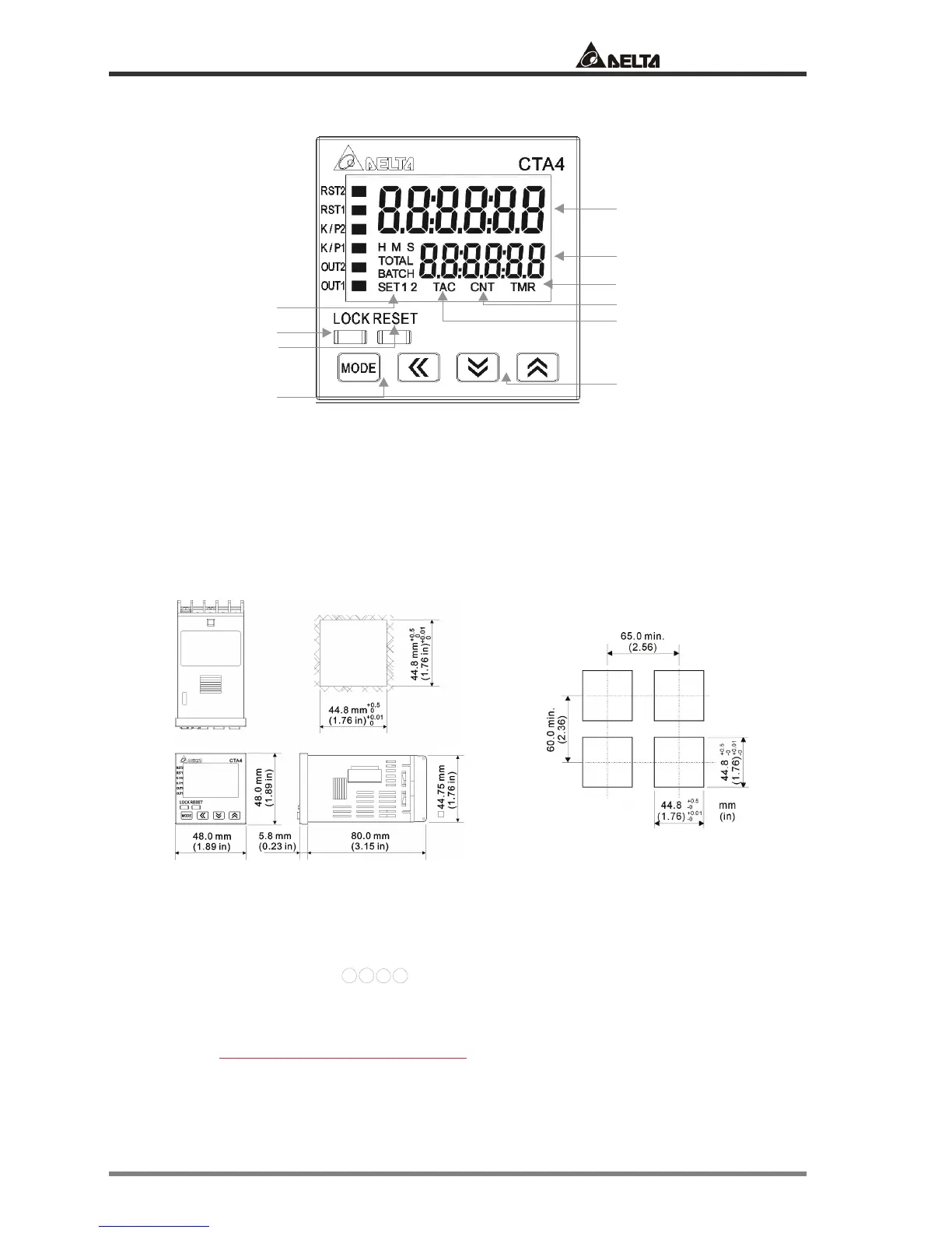
1.5 Dimensions
1.6 Terminal Definition
CTA combines the functions of timer, counter and tachometer; therefore, the definitions of input
terminals in different modes are slightly different. CTA has 4 terminals ready for inputs. Take the pins
in counter mode for example,
12
13
7
8
are for CP1 (A phase), CP2 (B phase) RST1 and RST2 inputs
(see figure 1).
The output terminals are for OUT1 and OUT2. OUT1 has two outputs, transistor output and relay
output, and the two outputs operate concurrently
. The type of OUT2 is determined by the model
name. For CTA4000A, OUT2 only offers transistor output with inductive load protection diode (see
figure 2). For CTA4100A, OUT2 only offers relay output (see figure 3).
 Loading...