EasyManuals Logo
Home>Delta Electronics>Measuring Instruments>CTA4

Delta Electronics CTA4 User Manual

Delta Electronics CTA4
25 pages
To Next Page IconTo Next Page
To Previous Page IconTo Previous Page
Page #24 background imageLoading...
Page #24 background image
CTA USER MANUAL
2007-05-09 - 24 - © DELTA ELECTRONICS, INC. ALL RIGHTS RESERVED
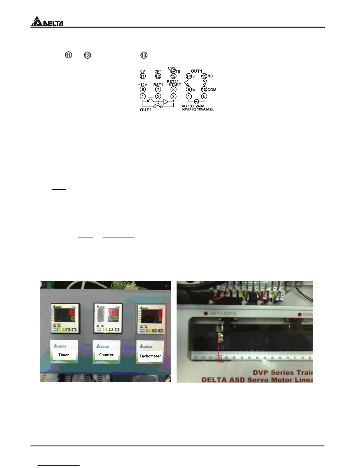
Output Wiring
Connect
0V, CP1 (phase A) and CP2 (phase B) to CN1 terminal on ASDA-A servo drive
Assume
The set value in the CTA counter is 160mm. When the counting reaches 160mm, an output signal will be given
to the knife for the cutting. See figure 2.
In the figure, we can see the diameter of the roller is 44.8mm
Delta encoder 1 phase = 2,500ppr
Calculate the pre-scale value
ppr
D
π
= Prescale
π: 3.1416
D: diameter of the roller
ppr: number of pulses per revolution of the encoder
Prescale =
ppr
D
π
=
2500
84414163 .x.
= 0.056mm/pulse
When the value in CTA = 2,858
2858 x 0.056 = 160mm (actual moving distance)
Figure 1
SV has to be 160mm
Figure 2
The servo drive stops at 100mm on the ruler before its
operation
100mm

Other manuals for Delta Electronics CTA4

Questions and Answers:

Question and Answer IconNeed help?

Do you have a question about the Delta Electronics CTA4 and is the answer not in the manual?

Delta Electronics CTA4 Specifications

General IconGeneral
BrandDelta Electronics
ModelCTA4
CategoryMeasuring Instruments
LanguageEnglish