Chapter 5 Trial operation and Tuning ASDA-A2
5-2 Revision February, 2017
Please contact with Delta if there is any vibration of the servo motor or unusual noise during
the operation.
Make sure the setting of the parameters is correct. Different machinery has different
characteristic, please adjust the parameter according to the characteristic of each machinery.
Please reset the parameter when the servo drive is in SERVO OFF status, or it may cause
malfunction.
When the relay is operating, make sure it can work properly.
Check if the power indicator and LED display works normally.
PWM is used to control 7.5 kW. Thus, when the temperature is lower than 40℃, the fan does
not work.
5.2 Applying Power to the Servo Drive
Please follow the instructions below.
A. Make sure the wiring between the motor and servo drive is correct.
1) U, V, W and FG have to connect to cable red, white, black and green respectively. If the
wiring is incorrect, the motor cannot work normally. The ground wire FG of the motor must
be connected to the ground terminal of the servo drive. Please refer to Chapter 3.1 and 3.2
for wiring.
2) The encoder cable of the motor has correctly connected to CN2: If users only desire to
execute JOG function, it is unnecessary to connect CN1 and CN3 (Please refer to Chapter
5.3). Refer to Chapter 3.1 and 3.5 for the wiring of CN2.
Caution: Do not connect the power terminal (R, S, T) to the output terminal (U, V, W) of the
servo drive. Or it might damage the servo drive.
B. Power circuit of the servo drive:
Caution: Wiring of 220 V servo drive is different from 400 V. Make sure the wiring is correct,
or it might damage the servo drive.
220V Servo Drive: Apply power to the servo drive. Please refer to Chapter 3.1.3 for power wiring.
400V Servo Drive: Apply power to the servo drive. Please refer to Chapter 3.2.3 for power wiring.
C. Power on:
220V Servo Drive: Power of the servo drive: including control circuit (L1c, L2c) and main
circuit (R, S, T) power.
400V Servo Drive: Power of the servo drive: including control circuit (DC24V, DC0V) and
main circuit (R, S, T) power.
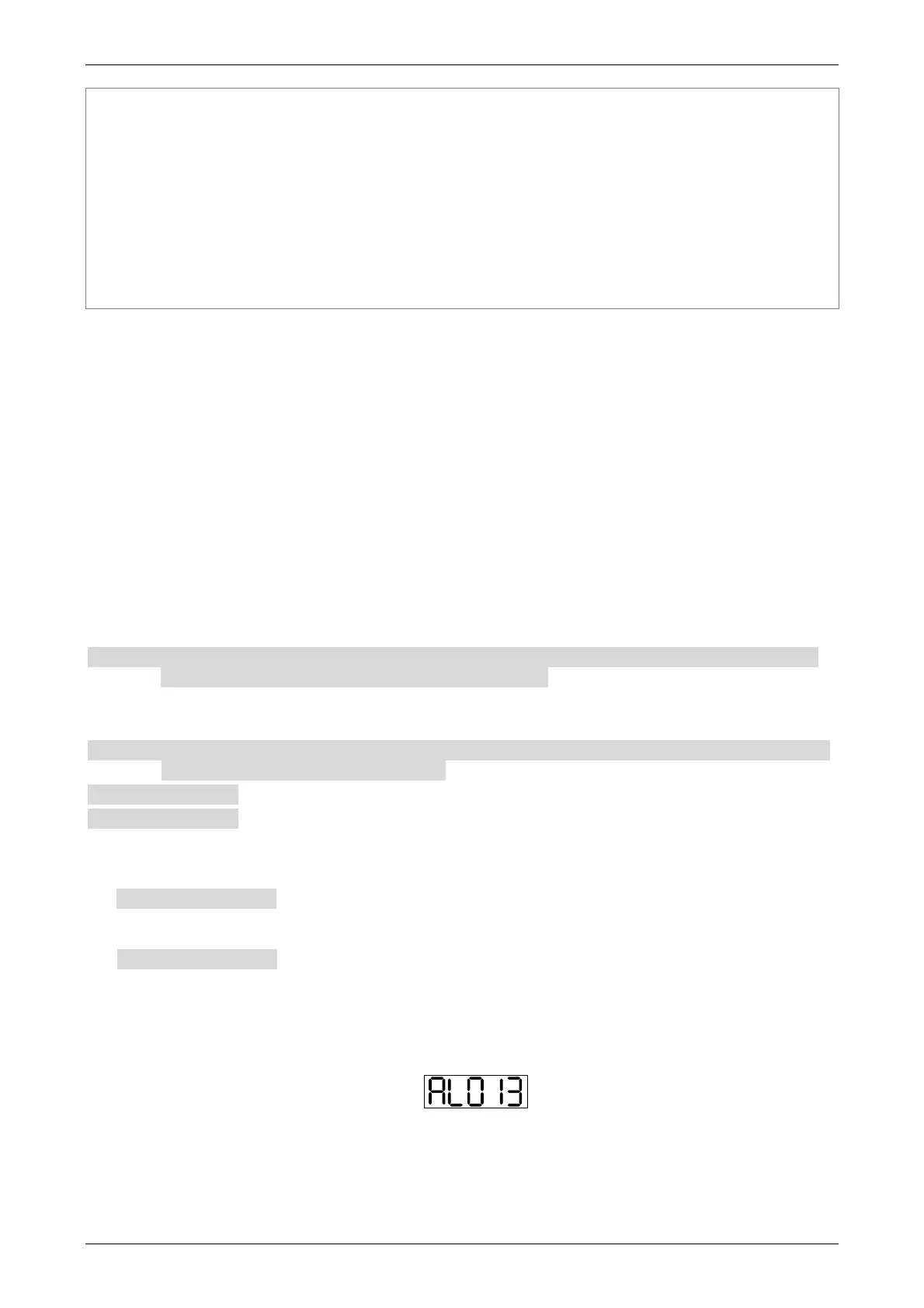
When the power is on, the display of the servo drive will be:
The digital input (DI6~DI8) of the default value is the signal of reverse limit error (NL), forward
limit error (PL) and emergency stop (EMGS), if not using the default setting of DI6~DI8,
adjusting the setting of P2-15~P2-17 is a must. Parameters could be set to 0 (disable this DI

 Loading...