EasyManua.ls Logo

Delta ASDA-A2 Series User Manual

Delta ASDA-A2 Series
721 pages
To Next Page IconTo Next Page
To Previous Page IconTo Previous Page
Page #207 background image
Chapter 6 Control Mode of Operation ASDA-A2
6-52 Revision February, 2017
6.6 Others
6.6.1 The Use of Speed Limit
The maximum speed in each mode is limited by internal parameters (P1-55), not matter it is in
position, speed or torque mode.
The issuing method of speed limit command and speed command is the same. The command
source could be external analog voltage or internal parameter (P1-09 ~ P1-11). Please refer to
Section 6.3.1 for descriptions.
Speed limit can be used in torque mode (T) only. It is used for limiting the motor speed. When the
command in torque mode is issued by external analog voltage, DI signal is enough and can be
regarded as SPD0~SPD1 which is used to determine the speed limit command (internal
parameters). If the DI signal is not enough, speed limit command can be issued by analog voltage.
When the function of disable/enable limit function in P1-02 is set to 1, the speed limit function is
enabled. See the timing diagram as below.
6.6.2 The Use of Torque Limit
The issuing method of torque limit command and torque command is the same. The command
source could be external analog voltage or internal parameter (P1-12 ~ P1-14). Please refer to
Chapter 6.4.1 for descriptions.
Torque limit can be used in position mode (PT, PR) or speed mode (S). It is used for limiting the
motor torque output. When the command in position mode is issued by external analog voltage, DI
signal is enough and can be regarded as TCM0~TCM1, which is used to determine torque limit
command (internal parameters). If the DI signal is not enough, torque limit command can be issued
by analog voltage. When the function of disable/enable torque limit function in P1-02 is set to 1, the
torque limit function is enabled. See the timing diagram as below.

Table of Contents

Other manuals for Delta ASDA-A2 Series

Question and Answer IconNeed help?

Do you have a question about the Delta ASDA-A2 Series and is the answer not in the manual?

Delta ASDA-A2 Series Specifications

General IconGeneral
Enclosure RatingIP20
Control ModePosition, Speed, Torque
Communication InterfaceRS-485, CANopen
ProtectionOvercurrent, Overvoltage, Undervoltage, Overload, Overtemperature, Encoder error
Operating Temperature0°C to 55°C
Storage Temperature-20°C to 65°C
Humidity20% to 90% RH (non-condensing)
Altitude1000m max
Cooling MethodNatural cooling or forced air cooling
Encoder Feedback20-bit incremental encoder (standard), 17-bit absolute encoder (optional)

Summary

Chapter 1 Inspection and Model Explanation

1.1 Inspection

Pre-operation checks for product condition and functionality.

1.2 Product Model

Nameplate information and detailed model code explanation for ASDA-A2 and ECMA series.

1.3 Servo Drive and Corresponding Servo Motor

Matching specifications for servo drives and motors across different voltage series.

1.4 Each Part of the Servo Drive

Identification and function of various parts of the servo drive.

Chapter 2 Installation

2.1 Notes

Important notes on connections, voltage, and wiring.

2.3 Ambient Conditions of Installation

Environmental conditions required for installing the servo drive and motor.

2.4 Installation Direction and Space

Guidelines for correct mounting and ventilation space.

2.5 Specification of Circuit Breaker and Fuse

Recommended circuit breakers and fuses for various series.

2.6 EMI Filter Selection

Recommendations for EMI filters and installation precautions.

2.7 Selection of Regenerative Resistor

Guidelines for selecting regenerative resistors.

Chapter 3 Wiring

3.1 Connections - 220V series

Wiring information for 220V series servo drives.

3.1.1 Connecting to Peripheral Devices

How to connect external devices to the servo drive.

3.1.2 Connectors and Terminals of Servo Drive

Detailed description of servo drive connectors and terminals.

3.1.3 Wiring Method

Wiring methods for single-phase and three-phase power.

3.1.4 Specification of Motor Power Cable

Specifications for motor power cables.

3.1.5 Specification of Encoder Cable Connector

Specifications for encoder cable connectors.

3.2 Connections - 400V series

Wiring information for 400V series servo drives.

3.2.1 Connecting to Peripheral Devices

How to connect external devices to 400V series drives.

3.2.2 Connectors and Terminals of the Servo Drive

Detailed description of 400V series drive connectors and terminals.

3.2.3 Wiring Method

Wiring methods for 400V series servo drives.

3.3 Basic Wiring

Basic wiring diagrams for 220V and 400V series.

3.4 I/O Signal (CN1) Connection

Details on connecting I/O signals to the CN1 connector.

3.4.1 I/O Signal (CN1) Connector Terminal Layout

Pinout and layout of the CN1 connector.

3.4.2 Signals Explanation of Connector CN1

Explanation of signals for the CN1 connector.

3.5 CN2 Connector

Details on the CN2 connector for motor encoder connection.

3.6 Wiring of CN3 Connector

Information on wiring the CN3 connector for communication.

3.7 CN4 Serial Connector (USB)

Details on the CN4 serial connector for PC connection via USB.

3.8 CN5 Connector (Full-closed loop)

Information about the CN5 connector for full-closed loop applications.

3.9 CN6 Connector (CANopen)

Details on the CN6 connector for CANopen communication.

3.12 Standard Connection Example – 220V series

Standard wiring examples for the 220V series.

3.13 Standard Connection Example – 400V series

Standard wiring examples for the 400V series.

Chapter 4 Panel Display and Operation

4.1 Panel Description

Detailed explanation of the servo drive's front panel components and their functions.

4.2 Parameter Setting Procedure

Step-by-step guide for setting parameters using the front panel.

4.3 Status Display

Explanation of various status indicators and displays on the panel.

4.4 General Function

General operational functions accessible via the panel.

Chapter 5 Trial Operation and Tuning

5.1 Inspection without Load

Pre-operation checks on the motor and drive without load.

5.2 Applying Power to the Servo Drive

Correct procedure for applying power to the servo drive.

5.3 JOG Trial Run without Load

Procedure for testing motor operation in JOG mode without load.

5.4 Trial Run without Load (Speed Mode)

Steps for trial running the motor in speed mode without load.

5.5 Trial Run without Load (Position Mode)

Steps for trial running the motor in position mode without load.

5.6 Tuning Procedure

General procedure for tuning the servo system.

Chapter 6 Control Mode of Operation

6.1 Selection of Operation Mode

Description of single, dual, and multi-control modes.

6.2 Position Mode

Detailed explanation of position control mode.

6.3 Speed Mode

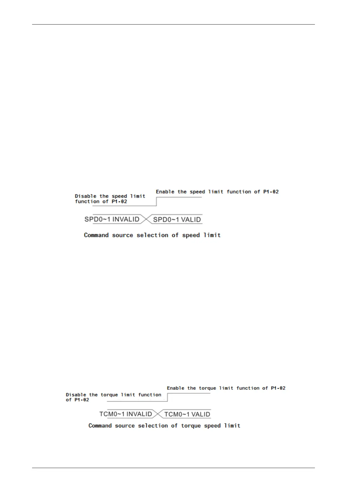
Detailed explanation of speed control mode.

6.4 Torque Mode

Detailed explanation of torque control mode.

6.5 Dual Mode

Explanation of dual mode operations.

Chapter 7 Motion Control

7.1 Motion Control Functions of ASDA-A2

Overview of the motion control capabilities of the ASDA-A2 series.

7.2 System Information

Information about system parameters, monitoring variables, and data arrays.

7.3 Description of Motion Axes

Explanation of the different motion axes and their attributes.

7.4 Description of PR Mode

Detailed description of the PR (Procedure) mode.

7.8 Homing Description of PR Mode

How to perform homing operations in PR mode.

7.10 Parameter Settings

Overview of parameters related to motion control and PR mode settings.

7.11 The Description of E-Cam Function

Detailed explanation of the Electronic Cam (E-Cam) function.

Chapter 8 Parameters

8.1 Parameter Definition

Explanation of parameter grouping and naming conventions.

8.2 List of Parameters

A comprehensive list of parameters, their abbreviations, functions, and related sections.

8.3 Parameter Description

Detailed descriptions of various parameters, categorized by group.

Chapter 10 Troubleshooting

10.1 Alarm of Servo Drive

List of servo drive alarms, their descriptions, corresponding DO signals, and servo status.

10.2 Alarm of CANopen Communication

Troubleshooting for CANopen communication alarms and corrective actions.

10.3 Alarm of Motion Control

Troubleshooting for motion control related alarms and corrective actions.

10.4 Causes and Corrective Actions

Detailed breakdown of common causes and corrective actions for various alarms.

10.5 Corrective Actions after the Alarm Occurs

General corrective actions for various alarm codes.

Related product manuals