Chapter 6 Control Mode of Operation ASDA-A2
6-58 Revision February, 2017
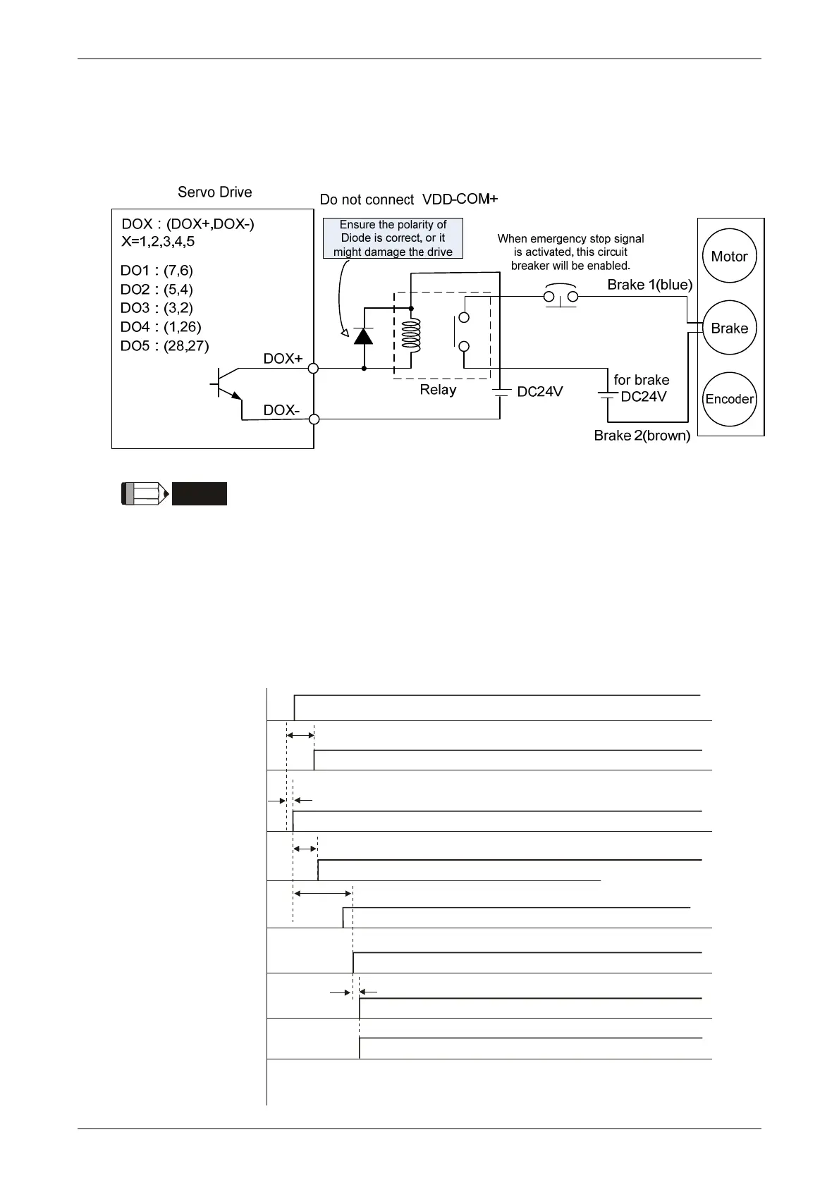
2. When Servo Off, has not reached the time set by P1-43 but the motor speed is slower than
the setting in P1-38, DO.BRKR is OFF (the brake is locked.).
The wiring diagram of using mechanical brake:
NOTE
1)Please refer to Chapter 3, Wiring.
2)The brake signal controls the solenoid valve, provides power to the
brake and enables the brake.
3)Please note that there is no polarity in coil brake.
4)Do not use brake power and control power (VDD) at the same time.
Timing diagram of control power and main power:
L1, L2
Control Circuit
Power
5V
Control Circuit
Power
R, S, T
Main Circuit
Power
BUS Voltage
READY
SERVO
READY
SERVO ON
(DI Input)
SERVO ON
(DO Output)
Position \ Speed \
Torque Command
Input
1 sec
> 0msec
800ms
2 sec
1 msec (min)+ P2-09)Response Filter Time of Digital Input (
Input available

 Loading...


