62
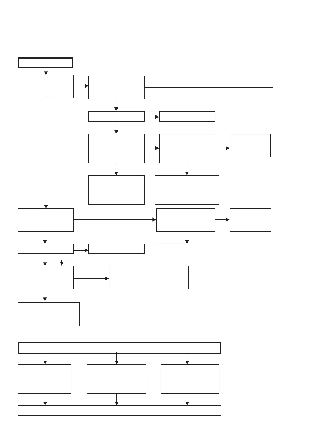
TROUBLE SHOOTING
1. POWER
1.1. Power not turn on
YES YES
YES
NO
NO
YES
NO
NO
When the power turned on,
does the ON/STANDBY
indicator on the front panel
ashing green?
Is the fuse blown?
About 10 seconds later,
does the ON/STANDBY
indicator on the front panel
turn lighting green ?
Check voltage of CN771 (4-
7PIN) of DIGITAL B'D while
the ON/STANDBY indicator
is ashing green.
Pull out connector (CN703) of
MAIN BD, and check "2. Errors
checking mode".
(Refer to 21 page.)
Power not turn on.
Is the fuse blown?
When the power turned on,
does the ON/STANDBY
indicator on the front panel
ashing red?
Is a DC 5V voltage being
supplied from the SMPS
B'D (BN601) to the DIGITAL
B'D?
Refer to 1.2.Fuse is blown.
Refer to 1.2. Fuse is blown.
Check circuitry and parts from CN751
on the DIGITAL B'D to the µ-com for
damage and shortcircuits, and replace
any defective parts.
Check "2. Errors
checking mode".
(Refer to 21
page.)
Are there any incomplete
connections in the connectors
connecting between the
various circuit boards?
Is a DC 5V voltage output
when the cord supplying the
power from the SMPS B'D
to the DIGITAL B'D (CN751)
is unplugged?
Check µ-com periphery
circuitry of DIGITAL B'D and
replace any defective parts.
Check circuitry and parts from
CN751 on the DIGITAL B'D
to the µ-com power supply for
damage and shortcircuits, and
replace any defective parts.
Connect the connectors properly.
To troubleshooting
6. SMPS.
(Refer to 75
page.)
NO
YES
YES
4,6,7 PIN : 0V
5 PIN : 3.3V
4,6,7 PIN : 3.3V
5 PIN : 0V
YES
NO
NO NO
Check for leaks or short
circuits in the primary side
parts, and replace any
defective parts.
Fuse is blown
Check for short circuits in the
rectier diodes and circuitry of
the secondary side rectifying
circuits, and replace any
defective parts.
After repairing, also replace the fuse.
Check for short circuits in
the power stabilizer unit's
regulator output terminal and
the ground, and replace any
defective parts.
1.2. Fuse is blown
YES
 Loading...