CD player
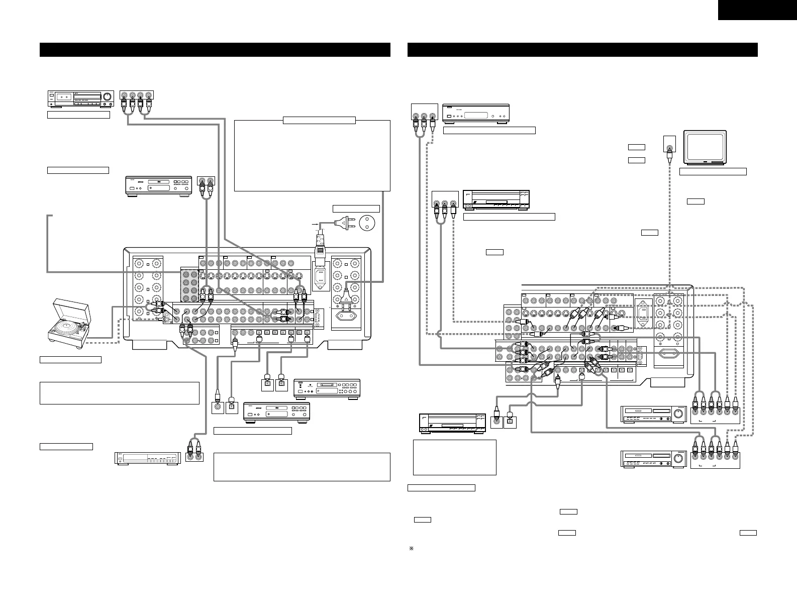
Connecting a CD player
Connect the CD player’s analog
output jacks (ANALOG OUTPUT)
to this unit’s CD jacks using pin
plug cords.
Connecting a turntable
Connect the turntable’s output cord to the AVC-A11SR’s PHONO jacks,
the L (left) plug to the L jack, the R (right) plug to the right jack.
NOTE:
This unit cannot be used with MC cartridges directly. Use a separate
head amplifier or step-up transformer.
If humming or other noise is generated when the ground wire is
connected, disconnect the ground wire.
Turntable
(MM cartridge)
Ground wire
AC cord (Supplied)
Connecting the pre-out jacks
Use these jacks if you wish to connect external power amplifier(s)
to increase the power of the front, center, surround and surround
back sound channels, or for connection to powered loudspeakers.
When using only one surround back speaker, connect it to left
channel.
Connecting the AC OUTLET
AC OUTLET
• SWITCHED (total capacity – 100 W)
The power to these outlets is turned on and off in conjunction
with the POWER switch on the main unit, and when the power
is switched between on and standby from the remote control
unit.
No power is supplied from these outlets when this unit’s power
is at standby. Never connect equipment whose total capacity is
above 100 W.
NOTE:
Only use the AC OUTLET for audio equipment. Never use them
for hair driers, TVs or other electrical appliances.
AC outlets (wall)
AC 230V, 50Hz
MD recorder, DAT deck or other component
equipped with digital input/output jacks
CD player or other component
equipped with digital output
jacks
Connecting the DIGITAL jacks
Use these for connections to audio equipment with digital output. Refer to
page 15 for instructions on setting this terminal.
Connecting a tape deck
Connections for recording:
Connect the tape deck’s recording input jacks (LINE IN or REC) to
this unit’s tape recording (OUT) jacks using pin plug cords.
Connections for playback:
Connect the tape deck’s playback output jacks (LINE OUT or PB)
to this unit’s tape playback (IN) jacks using pin plug cords.
CD recorder or Tape deck
• When making connections, also refer to the operating instructions of the other components.
Connecting a tuner
Connect the tuner’s output
jacks (OUTPUT) to this unit’s
TUNER jacks using pin plug
cords.
NOTES:
• Use 75 Ω/ohms cable pin cords for coaxial connections.
• Use optical cables for optical connections, removing the cap before
connecting.
Tuner
Connecting video components
• To connect the video signal, connect using a 75 Ω/ohms video signal cable cord. Using an improper cable can
result in a drop in picture quality.
• When making connections, also refer to the operating instructions of the other components.
TV or DBS/SAT tuner
LD player, CDV player, etc.
Monitor TV
Connecting a TV, DBS/SAT tuner
TV or DBS/SAT
• Connect the TV’s or DBS/SAT tuner’s video output jack (VIDEO OUTPUT) to the
(yellow) TV, DBS/SAT IN jack using a 75 Ω/ohms video coaxial pin plug cord.
• Connect the TV’s or DBS/SAT tuner’s audio output jacks (AUDIO OUTPUT) to the
TV, DBS/SAT IN jacks using pin plug cords.
AUDIO
VIDEO
Connecting a video disc player VDP
MONITOR OUT
• Connect the TV’s video input
jack (VIDEO INPUT) to the
MONITOR OUT jack
using a 75 Ω/ohms video
coaxial pin plug cord.
• The monitor TV can also be
connected in the same way to
the VIDEO MONITOR OUT-2
jack. Note, however, that the
AVC-A11SR’s on-screen display
signals are not output from this
jack. (See page 16.)
VIDEO
Note on connecting the digital
input jacks
• Only audio signals are input to
the digital input jacks. For
details, see page 15.
LD player or other component
equipped with digital output jacks
Video deck 2
Video deck 1
• There are three sets of video deck (VCR) jacks, so three video decks can be connected for simultaneous recording or video copying.
Video input/output connections:
• Connect the video deck’s video output jack (VIDEO OUT) to the (yellow) VCR-1 IN jack, and the video deck’s video input jack (VIDEO IN) to the
(yellow) VCR-1 OUT jack using 75 Ω/ohms video coaxial pin plug cords.
Connecting the audio output jacks
• Connect the video deck’s audio output jacks (AUDIO OUT) to the VCR-1 IN jacks, and the video deck’s audio input jacks (AUDIO IN) to the
VCR-1 OUT jacks using pin plug cords.
Connect the another video deck to the VCR-2 or VCR-3 jacks in the same way.
AUDIOAUDIO
VIDEO
VIDEO
Connecting a video decks
VDP
• Connect the video disc player’s video output jack (VIDEO OUTPUT) to the
(yellow) VDP IN jack using a 75 Ω/ohms video coaxial pin plug cord.
• Connect the video disc player’s analog audio output jacks (ANALOG AUDIO OUTPUT)
to the VDP IN jacks using pin plug cords.
• A DVD player can be connected to the DVD jacks in the same way.
• It is also possible to connect a video disc player, DVD player, video camcorder, game
machine, etc., to the V.AUX jacks.
AUDIO
VIDEO
Connecting a monitor TV
 Loading...