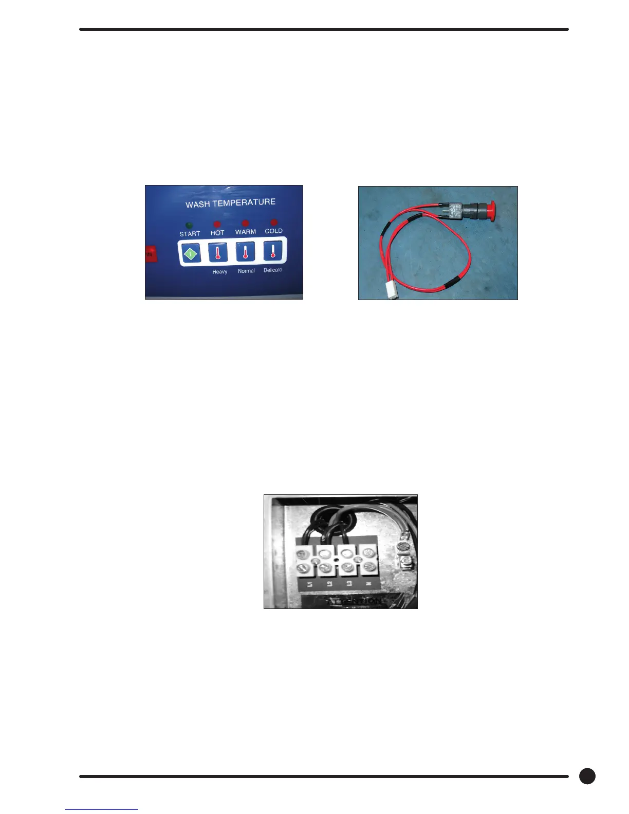
Emergency Stop Button Switch Assembly
The stop button is mounted on right side of machine. Remove the top and access the rear of button.
Remove the plastic retainer by unthreading CCW. The switch assembly will have to be removed by
pressing down on the plastic clip while pulling the switch body away from the stop button.
Power Connection Terminal Block
This terminal block sets at the very back of the control trough. Incoming power to the washer should
connect here. (see Electrical under Installation and Operation Section for exact connections)
Delta Variable Frequency Drive:
Main power is connected to terminals L1, L2, and L3 on the Delta drive. If the washer is connected to a
three phase source, there should be voltage present on all three terminals. If the washer is connected to
single phase power, there should be voltage present on terminals.
The voltage should measure 208 Volts to 240 Volts A.C. between phases and connected to if connected
to three phase). There is a tolerance of + 10% on the mains voltage (187 Volts to 264 Volts).
Temperature and Start
Display
Stop Button
Switch Assembly
Rear
83
Part # 8533-081-001 1/18

 Loading...