Connectors and Blocks
28
Connectors and Blocks
The development board provides the following connectors and blocks:
Embedded Module Connector, P10
The Digi Connect Wi-ME module does not provide pins 1-6.
JTAG Debugger Connector, P12.
-48V DC input to PoE module (Digi Connect ME must be connected to a Powering Device
for this feature.), P13
12V DC output from PoE module into Dev Board Power Supply, P14
Logic Analyzer Header, P3
See the figure titled "Board Layout and Connector Locations:" on page 22 for the location of the
connectors and blocks. The following sections describe the connectors and blocks.
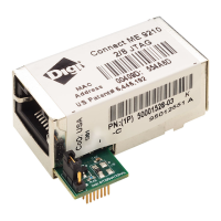
Embedded Module Connector, P10
The Digi Connect ME embedded module Connector is a 20-pin female vertical header that is
labeled P10 on the development board. See the following figure for pin orientation; see the
following table for pin assignments.
Note:
The figure shows the connector using the same orientation as shown in the figure titled
"Board Layout and Connector Locations:" on page 22.
 Loading...