Switches and Push Buttons
35
Switches and Push Buttons
The development board provides the following switches:
User PB1
User PB2
GPIO Switch Bank 1, SW3
Reset, SW4
Power On/Off SW5
See the figure titled "Board Layout and Connector Locations:" on page 22 for the location of the
switches. The following sections describe the switches.
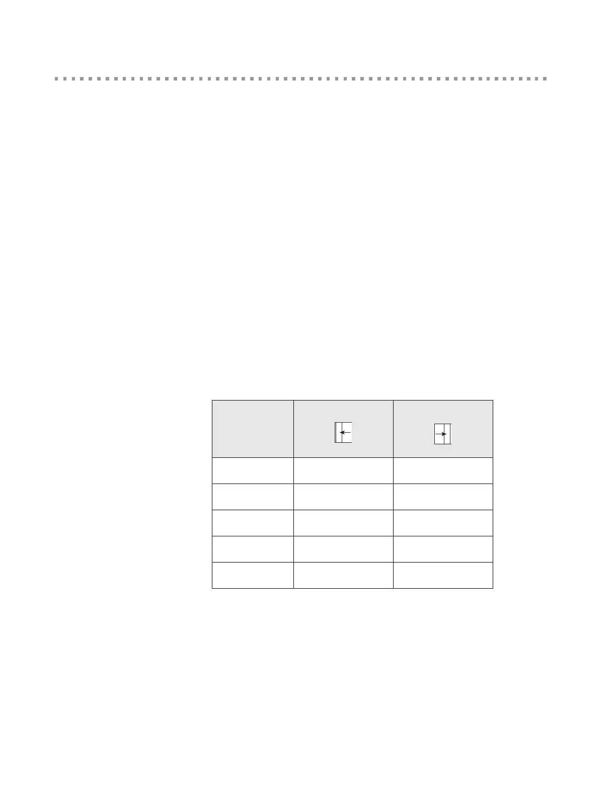
GPIO Switch Bank 1, SW3
GPIO Switch Bank 1, labeled SW3, is a set of five slide switches that allows the embedded module
to use either serial signals or GPIO signals to communicate with a device. With the switch to the left
position, the module’s signal is connected to the Serial Port1 RS232 transceiver. In the right
position, the module signal is connected to the appropriate pin of the GPIO Port P7.
GPIO Switch Bank 1 Settings
User Push Button 1, SW1
When switch number 1 is set to GPIO-1, pushing User Push Button 1, SW1, will drive GPIO-1
(module pin 13) low.
User Push Button 2, SW2
Pushing User Push Button 2, SW2, will drive module pin 18 low.
Switch
Number
Left Position
Right Position
1 DCD GPIO-1
2 CTS GPIO-2
3 DSR GPIO-3
4 RTS GPIO-4
5 DTR GPIO-5
 Loading...