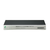
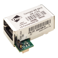
Module Pinout
42
Module Pinout
Where to Find More Information on Pin Configurations
The NS7520/NS9210 processors support 16 General Purpose I/O (GPIO) lines, some of which are
reserved for specific functions and some of which can be customized. For Digi Plug and Play
Firmware users, see the Digi Connect Family Users Guide for details on what Pin configurations are
available to you.
Module Pinout
The following table provides signal header pinout information for the Digi Connect ME, Digi
Connect ME 9210, and Digi Connect Wi-ME modules. Please refer to the color key below.
Table Notes:
The CAN Bus interface is available on the 8/16 Digi Connect ME 9210, Wi-ME 9210
variants.
When using the 8/16 ME 9210/ Wi-ME 9210 CAN Bus, the DTR (9210 signal GPIO 6) line
must be tri-stated. When the DTR signal (9210 GPO/I 6) is used, 9210 GPO/I 15 must be tri-
stated. These two 9210 signals are wired together on the 9210 modules.
The Digi Connect Wi-ME 9210 module does not provide pins 1-6.
When using I2C, make sure to put a 10k pull up on the SDA and SCL lines.
 Loading...