DVM-250/DVM-250Plus Installation Guide 860-00129-00 Rev C
Copyright © 2010-2015 Digital Ally, Inc. 3-5
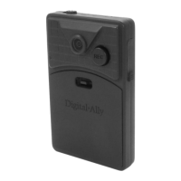
Interface Box Power Cable Installation
1. Plug the connector of the Vehicle Power cable into the IF Box.
2. Route the cable to a suitable location for electrical connection.
3. Remove 4 to 5 inches of the outer jacket at the bare end of the power
cable. Separate the braided shield from the individual conductors,
attach an electrical terminal to the end of the braided shield, and
attach the terminal to the chassis of the vehicle.
4. Connect the Red wire of the power cable to the vehicle +12Vdc and
the Black wire of this power cable connects directly to the vehicle’s chassis or a ground wire. It is
preferred that the power wire be tied in with DVM interface box connection with no
obstructions to battery such as a cutoff switch or charge guard system.
It is recommended that these connections are made directly to the engine
compartment battery wiring harness for best results. These wires should be used
ONLY for the DVM system and not be tapped into for installation of any other
equipment in the vehicle. Doing so could result in possible radio frequency
interference from the other equipment.
5. Connect the White wire to the ignition switch where +12vdc is only present when the vehicle
ignition key is in the ON position.
Do not connect the White wire directly to the vehicle battery. For proper operation
this wire must be connected to the vehicle ignition switch.
6. Secure the cable and the inline fuse housing using Velcro or standard tie wraps as required. The
cable contains a filter to help minimize unwanted RF noise and 3 amp fuse.
7. Re-connect the cable to the connector on the back of the DVM.
The IF Box provides multi-purpose sensor inputs that allow external devices
to trigger an event record in the mirror. It also provides an Output Alarm
to turn devices on or off when an event trigger occurs. Common external
sensors include; brake lights, turn signal indicators, reverse gear, covert
foot‐switch, or door sensors.
Determine the Device Trigger(s) Signal Level
For the administrator to configure each of the six (6) multi-purpose input sensors, the signaling from the
external device must be found and documented. Determine the signaling of each external device that
will be used and document the signal information on the Sensor Worksheet that has been provided on
page 7-14.
Reverse Gear Signal (DVM-250Plus only)
Tap into the reverse gear signal, with the vehicle started measure and record the DC voltage of
the signal with the vehicle in park; measure and note the DC voltage when the vehicle is in
reverse gear. Record both voltage levels on the Sensor Worksheet. Refer to the vehicle
manufacturer’s wiring diagram specific details for your vehicle.
Sensor #1 is reserved for the Reverse Gear Signal for use with the Backup camera option on
the DVM-250Plus.
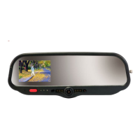
Step 4: Interface Box External Trigger Wiring
 Loading...