DVM-250/DVM-250Plus Installation Guide 860-00129-00 Rev C
Copyright © 2010-2015 Digital Ally, Inc. 5-11
Section - 4: Testing the Installation
1. Turn the vehicle ignition switch to the ON position. The vehicle does not have to be running.
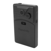
2. The DVM will begin the boot-up process; all 3-LEDs will flash in unison at a 1 second interval
until boot up is complete.
3. Once the boot-up process is complete, the Green LED will be lit indicating the DVM is powered
on, is ready, and in standby mode.
1. Press the RECORD button.
2. The Red status indicator will flash to indicate the manual event is being
recorded.
3. After 10 seconds, press the RECORD button to stop the manual event record.
4. The Red status indicator will extinguish, indicating the DVM has returned to standby mode.
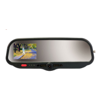
1. Start the vehicle and leave the transmission in Park.
2. Apply the brake and put the transmission into Reverse gear.
3. The LCD monitor will turn on and the live-video from the backup camera will be displayed.
4. The Red status indicator will begin flashing at 3 second intervals, indicating the back-up event is
being recorded.
5. Put the transmission back into Park.
6. The LCD monitor will turn off and the Red status indicator will extinguish, indicating the DVM has
returned to standby mode.
The Administrator is able to provide you with a configuration for the DVM to test Input Sensor Triggers
that have been connected to the DVM system. Below are basic instructions for testing these ports:
1. Activate a trigger input device to begin an Event Record.
2. The Red status indicator will flash to indicate the manual event is being recorded.
3. If the DVM was configured to activate the Output Alarm for the input trigger verify for the
proper functionality.
4. After the Event Record Time has been reached the event record will stop.
5. The Red status indicator will extinguish, indicating the DVM has returned to standby mode.
6. Repeat this process above for each of the input devices.
Section - 5: Support
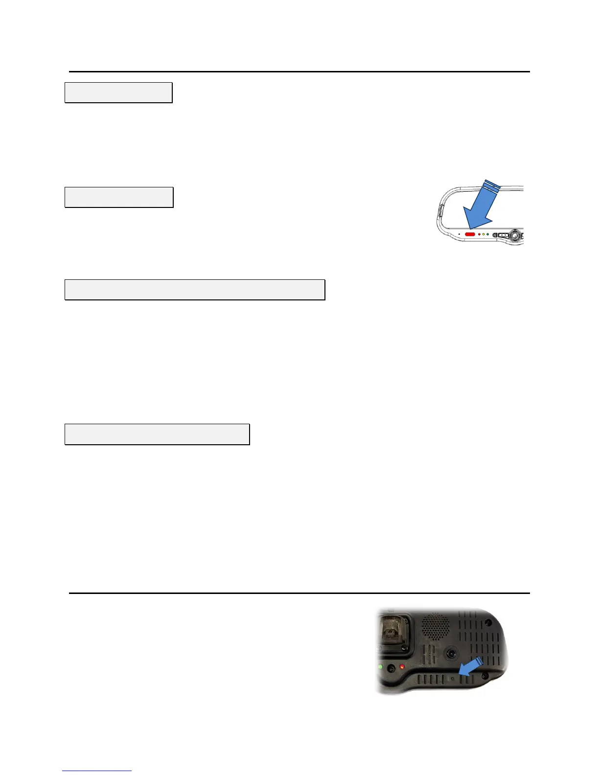
How to Reset the DVM-250 System
Using a small blunt object such as a small eye-glass screwdriver or
a paper clip, press the reset button on the DVM. The reset button
is recessed and located on the road facing, driver’s side of the
housing as shown here.
Viewing the Backup Camera (DVM-250Plus only)
Sensor/Output Alarm Testing
 Loading...