A3/A3Pro
User Manual
©
2016 DJI. All Rights Reserved.
5
A3 and A3 Pro Parts
Flight Controller
Feature Highlights
1. Independent CAN1 and CAN2 ports and API Serial port for the SDK. The CAN1 port is used to
connect the GPS-Compass Pro and DJI devices (e.g. RTK GPS) while the CAN2 port is used
to connect SDK devices.
2. Built-in inertial sensors for the measurement of aircraft attitude and built-in pressure sensor for
the detection of aircraft altitude.
3. Support for multiple receiver types. If used with the DJI Lightbridge 2, the A3 has direct access
to features in the DJI GO app such as Intelligent Flight Modes.
4. M1 to M8 are used to connect the ESCs of the aircraft and iESC for DJI Intelligent ESC
communication.
5. 4 independent and congurable output ports and 4 I/O ports. These ports can be customized
and connect other DJI devices (e.g. DJI Zenmuse Z15 gimbals, DJI Intelligent Landing Gear) or
SDK devices.
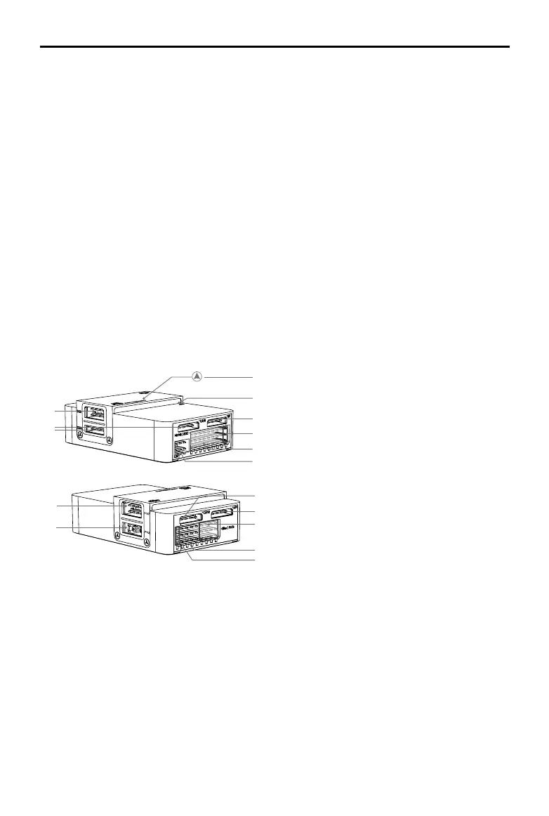
Port Diagram
4
5
6
7
8
3
1
2
9
10
12
11
13
14
15
1. IMU1 Port
Communicates with the IMU Pro module.
2. CAN1 Port
Dedicated DJI CAN-Bus port. Communicates
with the A3 GPS-Compass Pro or other DJI
devices (e.g. Real Time Kinematic (RTK) GPS
system).
3. Orientation Arrow
The FC module should be mounted with
the arrow pointing in the specified direction
(Orientation can be set in the DJI Assistant 2).
4. Status Indicator
Indicates the status of the ight controller and
triple modular redundancy system.
5. RF Port
Communicates with the DJI Lightbridge 2 Air
System.
6. iESC Port
Communicates with the DJI Smart ESC.
7. M1-M8 Pins
Connects to the corresponding ESC PWM
port for each motor.
8. LED Port
Communicates with the LED module.
9. IMU2 Port
Communicates with the IMU Pro module.
10. PMU Port
Derives power from the PMU.
11. CAN2
Communicates with an SDK device.
12. API Port
Communicates with an SDK device.
 Loading...