Vehicle Systems Hydraulic System Operation
39
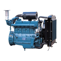
Shoe Type Brakes
Brakes With Automatic Adjustment (Right Side Shown)
(1) Upper adjustment link. (2) Cylinder assembly. (3) Piston.
(4) Secondary shoe. (5) Primary shoe. (6) Toggle lever.
(7) Support plate. (8) Lower adjustment link.
(9) Adjustment lever. (10) Adjustment screw.
(11) Adjustment spring.
When the brake pedal is pushed down, the master
cylinder sends brake fluid to wheel cylinder (2).
Wheel cylinder pistons (3) are pushed out and move
primary shoe (5) and secondary shoe (4). The brake
shoes move until they make contact with the brake
drum.
When the brake action first starts, primary shoe (5)
comes in contact with the brake drum as it is in
rotation. This contact of the primary shoe puts some
force on secondary shoe (4) to help put it in position
against the drum.
Automatic Adjustment
Brakes with automatic adjustment are adjusted on
the reverse braking action. In this example the drum
rotation is counterclockwise (in reverse) which
causes a counterclockwise rotation of the brake
shoes. Secondary shoe (4) moves away from
cylinder (2) that causes link (1) to move toggle lever
(6) in a clockwise rotation. Link (8) is connected to
the lower part of toggle lever (6) and to adjustment
lever (9). By this connection, adjustment lever (9) is
moved in a counterclockwise rotation.
When the brakes are released at the end of a
reverse brake application, adjustment spring (11)
puts adjustment lever (9) into its original position. If
the brake shoe lining has worn enough to let lever
(9) engage, a tooth on adjustment screw (10), lever
(9) will rotate screw (10) to put the brakes into the
correct adjustment.
Parking Brake
Parking Brake Adjustment
(1) Screw. (2) Nut. (3) Stop. (4) Lever. (5) Lock. (6) Nut.
2
1
3
4
5
6
IDCS212S
 Loading...