Frame assembly
Do not tighten the bolts while assembling the frame to
allow for spacer placement and frame adjustments. Tighten
all bolts securely when assembly is completed.
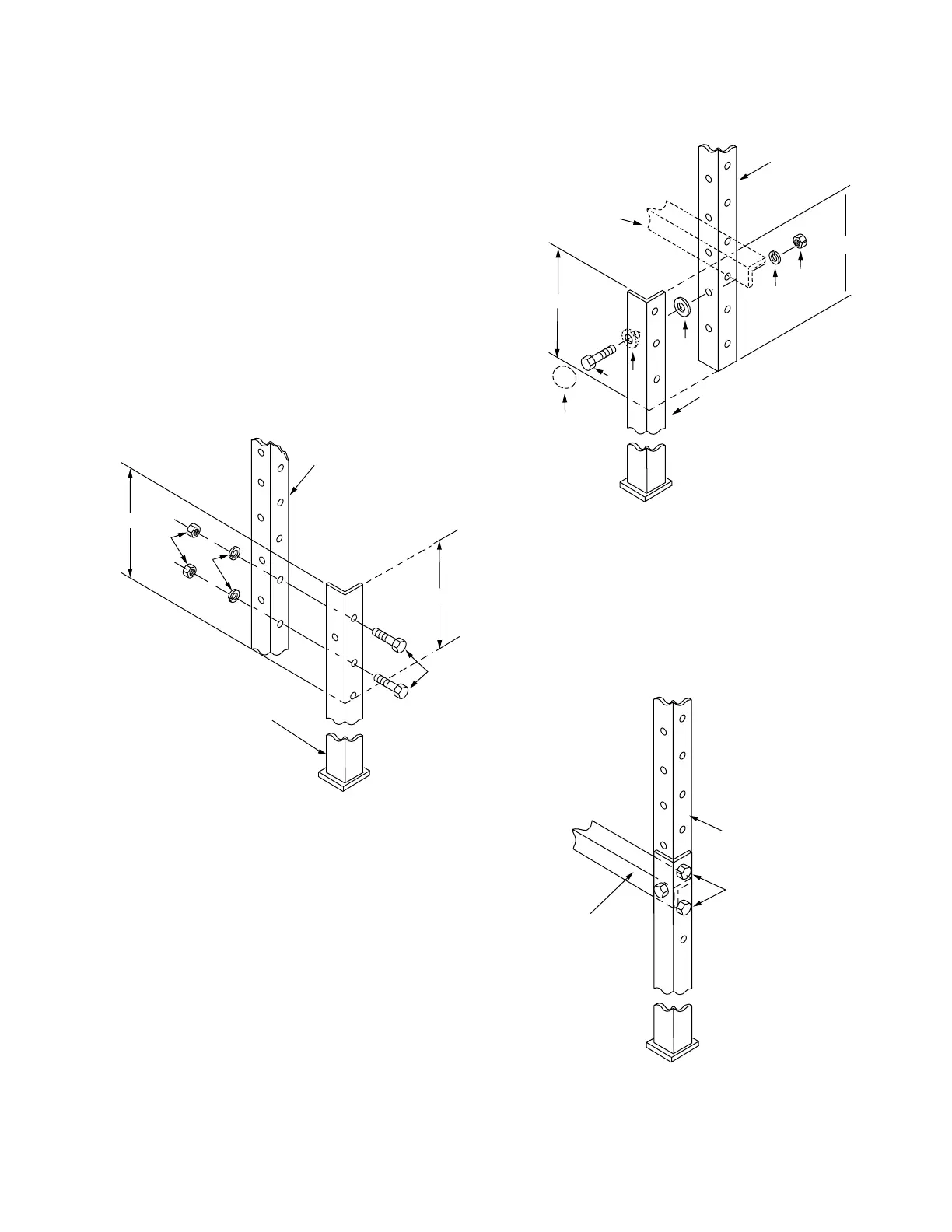
1. Overlap the upper and lower posts (Figure 4) as needed
to obtain the desired height of the frame. See the
Frame Height section of this manual.
A. Attach one upper post, left (Item 2) to one lower
post, left (Item 5) with 1.25” hex head capscrews
(Item 9), and secure with lockwashers (Item 14) and
.5” hex nuts (Item 13). See Figure 1 or 2.
B. Attach one upper post, right (Item 3) to one lower
post, right (Item 4) with 1.25” hex head capscrews
(Item 9), and secure with lockwashers (Item 14) and
.5” hex nuts (Item 13). See Figure 1 or 2.
2. Overlap the remaining upper and lower posts as
determined in step 1 while attaching the support angle
(Item 1).
A. Attach support angles (Item 1) to the remaining
upper posts (Items 2 and 3) and lower posts (Items4
and 5) with 1.75” hex head capscrews (Item 11),
with a spacer (Item 16) between the upper and lower
posts, and secure with lockwashers (Item 14) and .5”
hex nuts (Item 13). The caplug retainer (Item 18) and
caplug bolt cover (Item 17) are installed in the Item 1,
2, and 5 connection. See Figure 5.
B. Secure the upper posts (Items 2 and 3) and
lower posts (Items 4 and 5) with 1.25” hex head
capscrews (Item 9), and secure with lockwashers
(Item 14) and .5” hex nuts (Item 13). See Figures 4
and 6.
Figure 4. Attaching upper post to lower post.
OVERLAP
OVERLAP
LOWER
POST (Items 4 or 5)
UPPER
POST (Items 2 or 3)
14
13
9
Figure 5. Attaching support angle Item 1 to upper and
lower posts.
OVERLAP
UPPER
POST (Items 2 or 3)
OVERLAP
LOWER
POST (Items 4 or 5)
13
14
16
11
SUPPORT
ANGLE
(Item 1)
18
17
Figure 6. Securing upper and lower posts.
SUPPORT
ANGLE
(Item 1)
UPPER
FRAME
POST (Items 2 or 3)
Items 9, 11, and 13
7
SUBSTATION FRAME KNOVA59-1 AND KNOVA59-3 ASSEMBLY AND INSTALLATION INSTRUCTIONS MN280043EN January 2016
 Loading...


