Switchgear installation
NOVA recloser, DAS switch, VCS-3 switch, and TVS
sectionalizer installation
Refer to the appropriate manual for complete installation
instructions as follows:
•
S260-60-1 DAS15, DAS27, and DAS38 Three-Phase
Vacuum-Break Distribution Automation Switch Installation
and Operation Instructions
•
S260-62-1 VCS-3 Three-Phase Vacuum-Break Capacitor
Switch Installation and Operation Instructions
•
S270-30-1 TVS15, TVS27, and TVS38 Time-Voltage
Sectionalizer Installation and Operation Instructions
•
S280-42-1 NOVA15, NOVA27, and NOVA38 Three-Phase
Microprocessor-Controlled Installation and Operation
Instructions
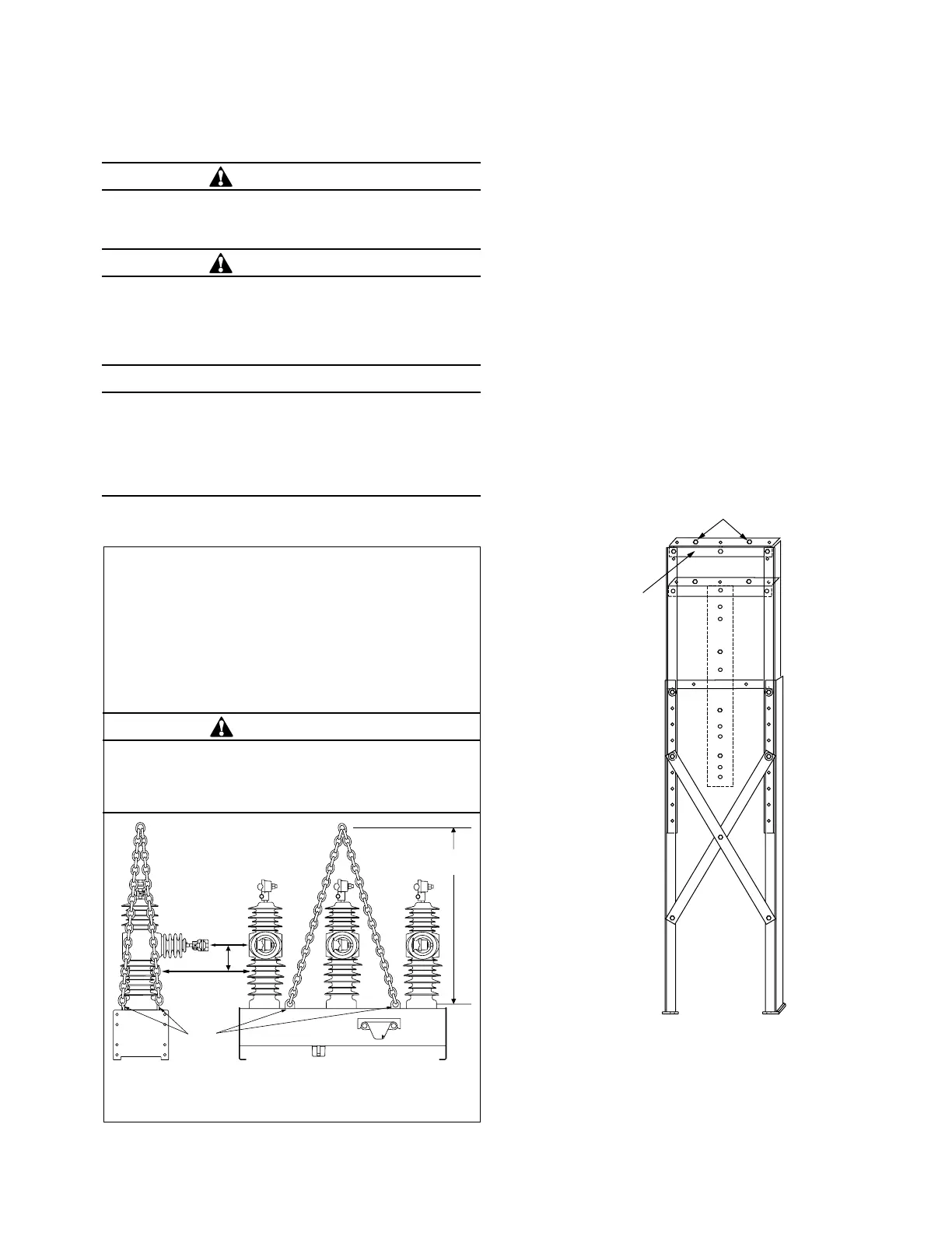
Mount the switchgear to the substation frame on both
sides to support angles (Item 1). Use 1.25” hex head
capscrews (Item 9) and secure with lockwashers (Item 14)
and .5” hex nuts (Item 13). See Figures 1 and 17.
Figure 17. Attaching NOVA recloser, DAS switch, VCS-3
switch, or TVS sectionalizer to substation frame.
Figure 16. Lifting instructions for the switchgear.
O
P
E
N
C
L
O
S
E
A
Cg
B
Lifting
Lugs
Moving the switchgear
The switchgear is shipped palletized (bolted onto a
pallet). When moving with a fork truck/lift, the switchgear
must remain bolted to the pallet to avoid damage to the
contact position indicator.
Lifting the switchgear
Follow all approved safety practices when making hitches
and lifting the equipment. Lift the unit smoothly and do
not allow the unit to shift.
A: Sling height for 15 kV and 27 kV with 125 BIL units: 914 mm (36 in)
Sling height for 27 kV with 150 BIL and 38 kV units: 1067 mm (42 in)
B: Center of gravity (Cg) is approximately 100 mm (4 in) below plane of lower
terminals.
WARNING
Falling equipment. Use the lifting lugs provided and follow
all locally approved safety practices when lifting and
mounting the equipment. Lift the unit smoothly and do not
allow the unit to shift. Improper lifting can result in severe
personal injury, death, and/or equipment damage.
G106.3
CAUTION
Personal injury. Sheds on epoxy encapsulation have
sharp edges. Wear protective gloves when handling the
unit. Failure to do so can result in cuts and abrasions.
T258.1
CAUTION
Tip-over hazard. High center of gravity. The substation
frame is a top-heavy structure with the switchgear
mounted. Secure the substation frame to the mounting
pad before mounting the switchgear. Failure to comply
can cause the unit to tip over, damaging the frame and
switchgear.
T300.0
CAUTION
Tip-over hazard. High center of gravity. Use a 4-point
hitch to prevent switchgear from overturning during lift-
ing operations. Improper lifting can result in personal
injury or equipment damage.
T297.0
11
SUBSTATION FRAME KNOVA59-1 AND KNOVA59-3 ASSEMBLY AND INSTALLATION INSTRUCTIONS MN280043EN January 2016
 Loading...


