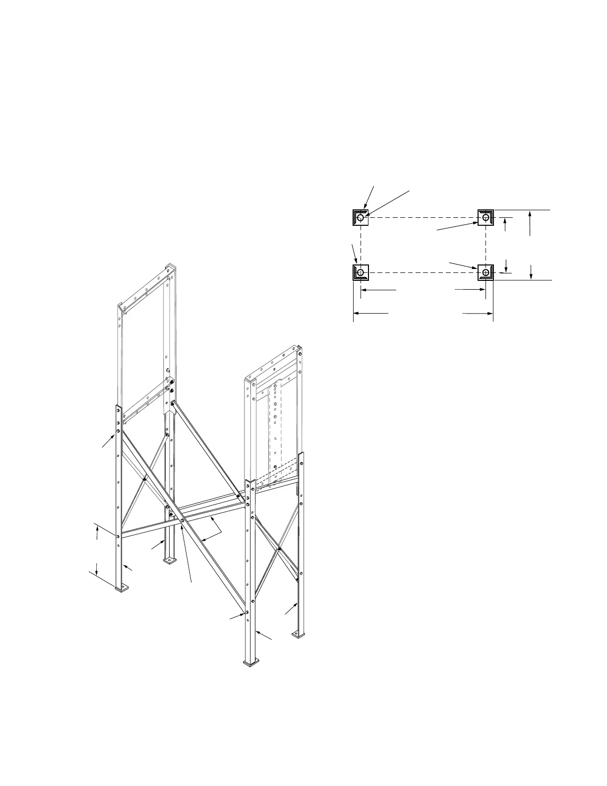
7. Attach the upper ends of the long cross braces (Item7)
to the upper posts (Items 2 and 3) and lower posts
(Items 4 and 5). Use 1.50” hex head capscrews (Item
10), and secure with lockwashers (Item 14) and .5” hex
nuts (Item 13). See Figure 11.
8. Attach the lower ends of the long cross braces (Item7)
to the lower posts (Items 4 and 5), with 1.25” hex head
capscrews (Item 9), and secure with lockwashers (Item
14) and .5” hex nuts (Item 13). See Figure 11.
9. Attach the long cross braces (Item 7) at their midpoint
with 1.25” hex head capscrews (Item 9), and secure
with lockwashers (Item 14) and .5” hex nuts (Item 13)
See Figure 11.
10. Check frame alignment and securely tighten all nuts
and screws.
Frame installation
Install the substation frame on the constructed mounting
pad. See the Frame Foundation section of this manual.
Firmly tighten all of the substation assembly hardware after
attaching the frame to the mounting pad. See Figure12.
Figure 11. Attaching long cross braces (Item 7).
5
9, 13, 14
7
10, 13, 14
400 mm
(15.75 in)
9, 13, 14
4
4
5
Figure 12. Installing substation frame on mounting pad.
552 mm
(21.75 in)
457 mm
(18 in)
1060 mm (41.75 in)
965 mm (38 in)
19 mm (3/4") Holes
for 16 mm (5/8") Anchor Bolts
Item 4
Item 4
Item 5
Item 5
9
SUBSTATION FRAME KNOVA59-1 AND KNOVA59-3 ASSEMBLY AND INSTALLATION INSTRUCTIONS MN280043EN January 2016
 Loading...


