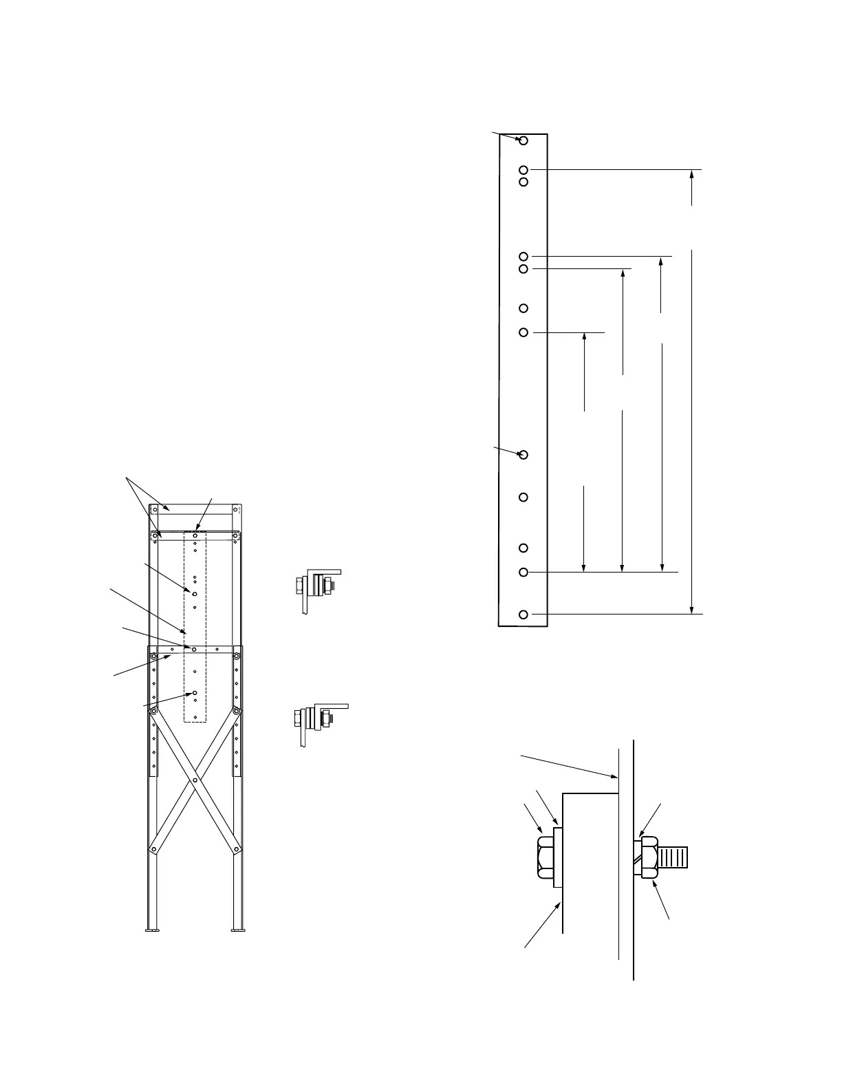
Control installation
Attach the control mounting strap (Item 8) to either one of
the narrow frame sides. See Figures 13 and 14.
1. Attach the control mounting strap (Item 8), at the hole
13 mm (.5 in) from the end (this is the top end), to
the middle support angle (Item1) with 1.75” hex head
capscrews (Item11). Secure with lockwashers (Item14)
and .5” hex nuts (Item 13). Use two spacers (Item16);
placement is determined by control type.
2. Attach the control mounting strap (Item 8), through
the hole 26.75” from the top end of the strap, to the
lower support angle (Item 1) with 1.75” hex head
capscrews (Item 11). Secure with lockwashers (Item 14)
and .5” hex nuts (Item 13). Use two spacers (Item 16);
placement is determined by control type.
3. Mount the control to the control mounting strap
(Item8). Measure the strap to determine where to
mount the control. Use 2.5” hex head capscrews
(Item12) and washers (Item 15), and secure with
lockwashers (Item 14) and .5” hex nuts (Item 13). See
Figures 13, 14, and 15.
Figure 15. Attaching control to mounting strap (Item 8).
12
15
14
13
CONTROL MOUNTING STRAP
(Item 8)
CONTROL
BRACKET
286 (11.25)
368 (14.5)
876 (34.5)
927 (36.5)
1016 (40)
13 (.5)
Attach to frame
679 (26.75)
Type Form 6 and Form 4C
(double-size cabinet)
940 (37)
Type FXA, FXB,
and
Form 4C
(single-size
cabinet)
511 (20.125)
Type Form 6
665 (26.25)
76 (3)
Dimensions shown: Top-to-hole on left, mounting holes on right.
All dimensions are mm (in). (Dimensions approximate).
Type Form 5
640 (25.25)
260 (10.25)
Figure 14. Control mounting strap (Item 8). (Only stan-
dard control mounting locations are shown.)
Figure 13. Attaching control mounting strap (Item 8) to
sub-station frame.
11, 13, 14, 16;
See detail.
11, 13, 14, 16;
See detail.
Item 1
Item 1
Item 8
12, 13, 14, 15
12, 13, 14, 15
For Form 4, Form 5,
and Pole-Mount Form 6:
For Rack-Mount Form 6:
10 SUBSTATION FRAME KNOVA59-1 AND KNOVA59-3 ASSEMBLY AND INSTALLATION INSTRUCTIONS MN280043EN January 2016
 Loading...


