Frame foundation
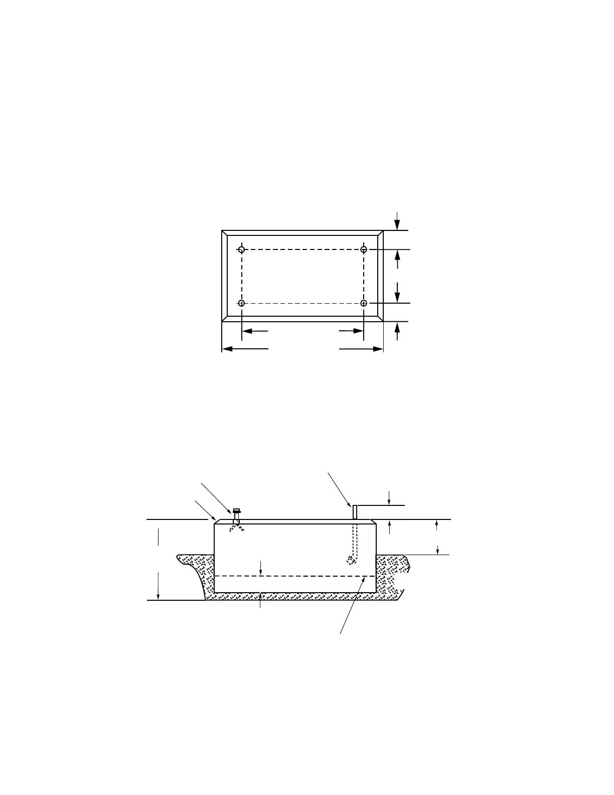
A mounting pad must be constructed for proper support
of the switchgear and substation frame. Concrete slabs
can be fabricated by a local concrete products firm. See
the dimensions in the plan and profile views of Figure3.
The overall weight of the substation frame is approximately
118kg (260lbs).
Figure 3. Location of anchoring holes and hardware in substation frame mounting pad.
Profile View
203 mm (8 in)
203 mm (8 in)
Plan View
457 mm (18 in)
1371 mm (54 in)
965 mm (38 in)
457 mm
(18 in)
102 mm (4 in)
152 mm (6 in)
51 mm (2 in) min.
Finished Grade
Bevel 25 mm (1 in)
Welded Wire Fabric Reinforcement
(102 mm (4") squares of No. 13 wire min.)
16mm (5/8") Threaded Insert
16 mm (5/8") std galvanized
machine bolt and flat washer
(alternative anchoring method)
4 SUBSTATION FRAME KNOVA59-1 AND KNOVA59-3 ASSEMBLY AND INSTALLATION INSTRUCTIONS MN280043EN January 2016
 Loading...


