25-75 kW
User's and Installation Guide
29
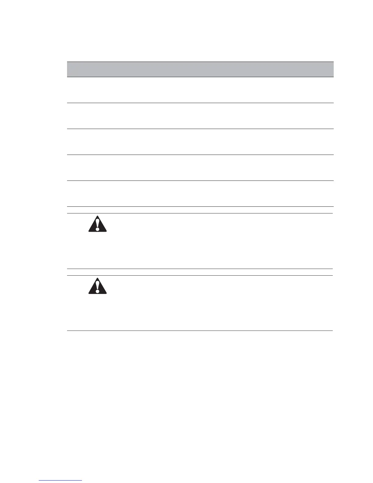
See the following table for power cable terminations.
Table3-8:UPSPowerCableTerminations
Terminalfunction Terminal Function TighteningtorqueNm
AC input to UPS rectifier MAINS INPUT L1,L2,L3,N
Check the tightening torque
from the connector label.
AC input to bypass
BYPASS
INPUT
L1,L2,L3,N
Check the tightening torque
from the connector label.
UPS output OUTPUT L1,L2,L3,N
Check the tightening torque
from the connector label.
DC input from external
battery to UPS
BAT
battery+, battery–
Check the tightening torque
from the connector label.
Protective Earth PE PE
Check the tightening torque
from the connector label.
NOTE
Externalovercurrentprotectionisnotprovidedbythisproduct,butisrequiredbycodes.RefertoTable3-6:
Minimumrecommendedmulti-corecableandfusesizesforwiringrequirements.Ifanoutputlockabledisconnect
isrequired,itistobesuppliedbytheuser.
CAUTION
Toreducetheriskoffire,connectonlytoacircuitprovidedwithmaximuminputcircuitbreakercurrentratings
fromTable3-7:Ratedandmaximumcurrentsforratedpowerandvoltageinaccordancewiththenationaland
local installation rules.
The line-to-line unbalanced output capability of the UPS is limited only by the full load per phase current
values for AC output to critical load shown in Table 3-7: Rated and maximum currents for rated power and
voltage. The recommended line-to-line load unbalance is 50 % or less.
Source Protection for the AC Input to Bypass should suit the characteristics of the load and take account of
effects such as Inrush or Starting Current. Bypass and output overcurrent protection and bypass and output
disconnect switches are to be provided by the user.
For UPS wiring diagrams, see Chapter 2.1 Looking inside the UPS system.
 Loading...


