Eaton 9E UPS (40–60 kVA, 208/220V) Installation and Operation Manual P-164000058—Rev 4 www.eaton.com/powerquality 7-1
Chapter 7 Communication
This chapter describes the communication features of the Eaton 9E UPS. For terminal wiring information, see
paragraph 3.2.3 and paragraph 4.11. For location of the customer interface panel and terminals, see Figure 4-10
and Figure 4-11.
7.1 Mini-Slot Cards
The Eaton 9E UPS has two standard, factory-installed Mini-Slot communication bays. See Figure 4-10 for bay
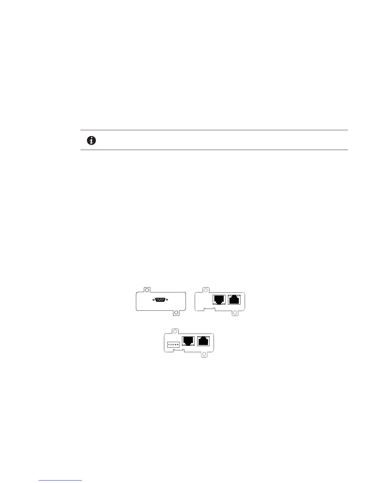
locations. The UPS is compatible with the following Mini-Slot cards (see Figure 7-1):
l
Network Management Card and Modbus/Jbus – provides remote monitoring through a Web browser
interface, e-mail, and a network management system (NMS) using SNMP and connects to a twisted-pair
Ethernet (10/100BaseT) network. The card also provides direct integration of UPS information (meters and
status) to a Building Management System (BMS) using the Modbus RTU protocol.
l
Network Management Card – provides remote monitoring through a Web browser interface, e-mail, and a
network management system (NMS) using SNMP and connects to a twisted-pair Ethernet (10/100BaseT)
network.
l
Relay Card – MS – two types of interfaces via a DB9 connector are available with this card. Dry contact
mode provides a simple way to transmit UPS information to an alarm system, PLC, or computer system via
dry relay contacts. The transmitted information is load powered, load on bypass, load on battery, load on
utility, battery fault, and low battery. RS232 mode provides an RS232 interface for connection to a PC or to a
UPS Control display unit. Jumpers are used to select the interface (contacts or RS232).
LAN and telephone drops for use with Mini-Slot connectivity cards must be supplied by facility planners or the
customer.
For installation and setup of a Mini-Slot card, contact an Eaton service representative (see paragraph 1.8). Refer
to the manual supplied with the Mini-Slot card for user instructions.
Figure 7-1. Optional Mini-Slot Cards
7.2 Building Alarm Monitoring
This standard feature lets you connect the UPS to your building alarms, such as smoke detectors or
overtemperature alarms. The customer interface terminals for external connections are located inside the UPS.
Use twisted-pair wires for each alarm input and common.
The building alarms can be programmed to display the alarm functional name.
NOTE Only one Network Management Card or Network Management Card and Modbus/
Jbus can be used at one time.
Relay Card – MS
Network Management Card
Network Management Card and
Modbus/Jbus
 Loading...