UPS System Installation
4-18 Eaton 9E UPS (40–60 kVA, 208/220V) Installation and Operation Manual P-164000058—Rev 4 www.eaton.com/powerquality
4.11.2 Installing Parallel Pull Chain and CAN Control Wiring and Connections
To install wiring:
1. Verify the UPS system is turned off and all power sources are removed. See Chapter 6, “UPS Operating
Instructions,“ for shutdown instructions.
2. To locate the appropriate terminals and review the wiring and termination requirements, see
paragraph 3.2.3, Table 4-2, Figure 4-10, Figure 4-11, and Figure 4-16.
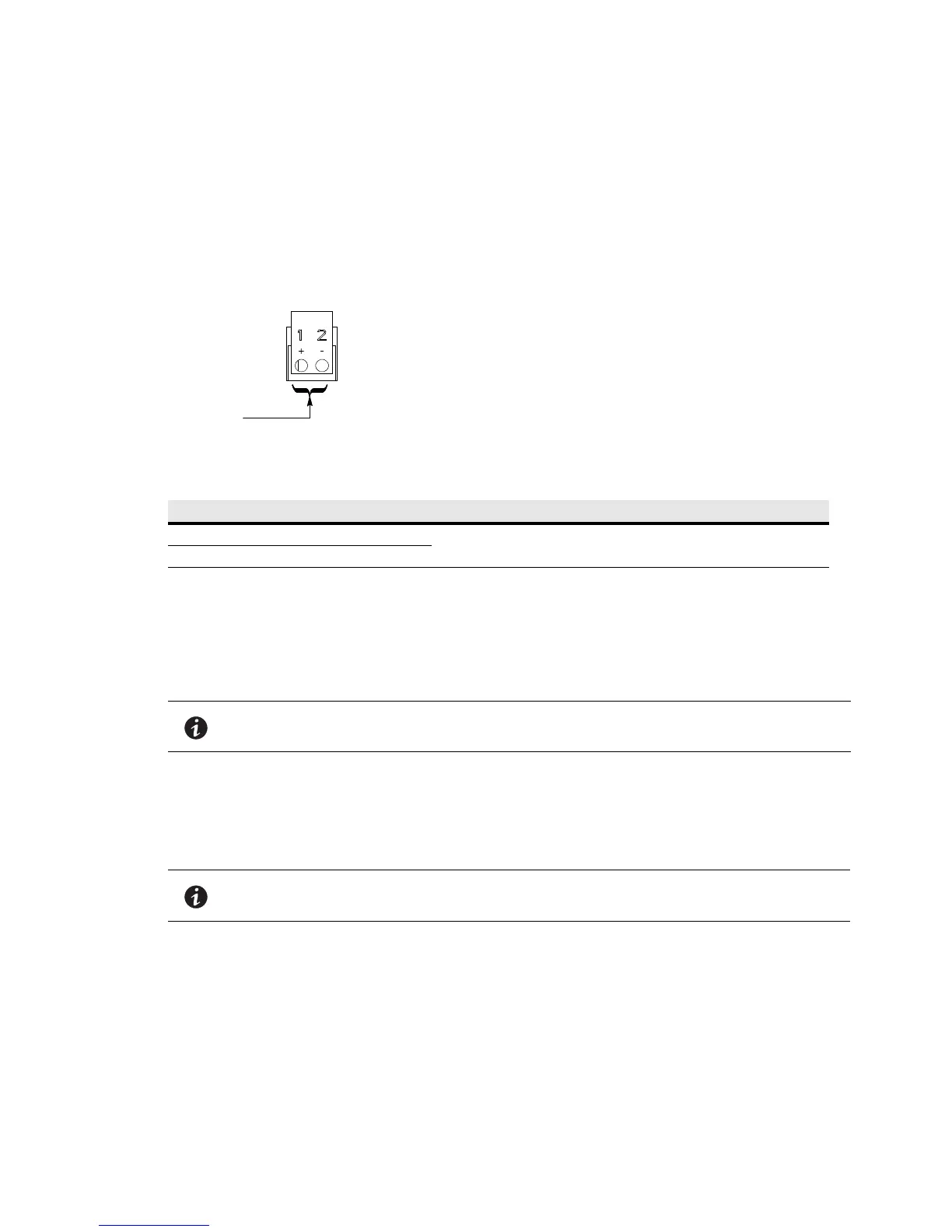
Figure 4-16. Pull Chain Terminal Block Connector Assignments
3. Route the wiring to the terminal block:
a. If not already removed, remove the power terminal cover right and left sides (see Figure 4-9). Retain
the cover top and hardware for later use.
b. If not already removed, remove the power terminal cover top. Retain the cover top and hardware for
later use.
c. Remove the screws securing the top rear panel (see Figure 4-10). Supporting the panel, tilt the panel
away from the cabinet and disconnect the fan connector from the wiring harness.
d. Remove the panel. Retain the panel and hardware for later use.
e. Remove the interface terminal cover (see Figure 4-13). Retain the cover and hardware for later use.
f. Punch or drill a hole in the power terminal cover base (see Figure 4-5, Figure 4-6, and Figure 4-14) for
the interface wiring conduit.
g. Route the wiring along the interface wiring channel (see Figure 4-14) to the wiring access
(see Figure 4-15). Secure the wiring to the four mounting clips provided using Zip ties.
h. Supporting the top rear panel at the back of the cabinet, reconnect the fan connector to the wiring
harness.
i. Reinstall the top rear panel by tilting into position and securing the panel using the retained hardware.
j. Reinstall the power terminal cover top using the retained hardware.
Table 4-2. Pull Chain Connections
Pull Chain Terminal Name Description
1 Pull Chain +
Output: Backup control for parallel operation.
2 Pull Chain –
NOTE The lower fan is attached to the top rear panel.
NOTE Conduit and wiring enter from the bottom of the conduit landing plate.
 Loading...