UPS System Installation
4-14 Eaton 9E UPS (40–60 kVA, 208/220V) Installation and Operation Manual P-164000058—Rev 4 www.eaton.com/powerquality
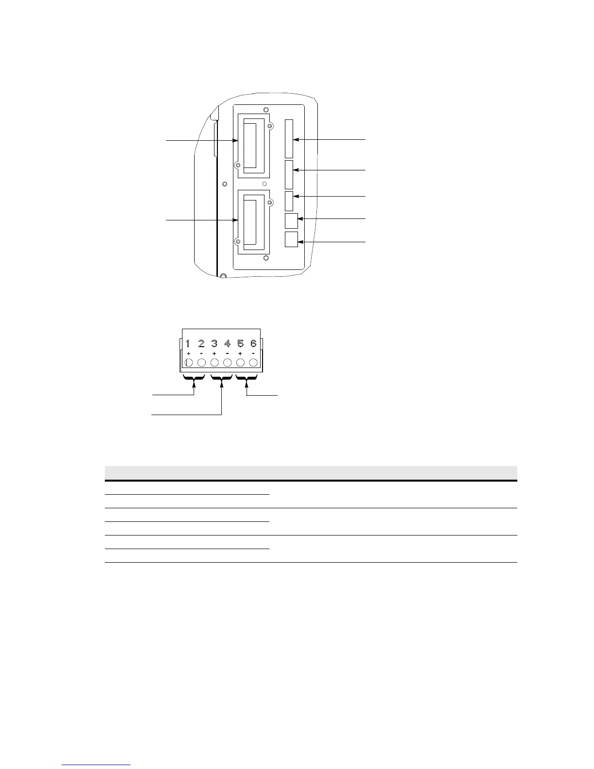
Figure 4-11. Interface Terminal Detail (Terminal Cover Removed)
Figure 4-12. Building Alarm Terminal Block Connector Assignments
3. Route the wiring to the terminal block:
a. If not already removed, remove the power terminal cover right and left sides (see Figure 4-9). Retain
the cover top and hardware for later use.
b. If not already removed, remove the power terminal cover top. Retain the cover top and hardware for
later use.
Table 4-1. Building Alarm Connections
Building Alarm Terminal Name Description
1 Building Alarm 1 +
Input: Programmable UPS alarm, activated by a remote dry contact closure.
2 Building Alarm 1 –
3 Building Alarm 2 +
Input: Programmable UPS alarm, activated by a remote dry contact closure.
4 Building Alarm 2 –
5 Building Alarm 3 +
Input: Programmable UPS alarm, activated by a remote dry contact closure.
6 Building Alarm 3 –
Mini-Slot
Communication Bay 1
Mini-Slot
Communication Bay 2
REPO Terminals
Parallel CAN Output (RJ45)
Parallel CAN Input (RJ45)
(See Figure 4-19 for Detail)
Building Alarm
(See Figure 4-12 for Detail)
Pull Chain Terminals
Building Alarm 1
UPS
Building Alarm 2
Building Alarm 3