UPS System Installation
4-6 Eaton 9E UPS (40–60 kVA, 208/220V) Installation and Operation Manual P-164000058—Rev 4 www.eaton.com/powerquality
4.3 Installing Power Terminal Cover Base
To install the Power Terminal Cover Base:
1. Locate the terminal cover base (see Figure 4-5) from the parts kit.
2. If installing wiring using conduit, proceed to Step 3; otherwise, proceed to Step 4.
3. Punch or drill holes in the bottom of the power terminal cover base (see 4-5 and 4-6) for the AC input,
output, bypass, DC input, REPO conduit as required.
4. Using the hardware provided, install the terminal cover base to the back panel of the UPS using the
existing cabinet screw holes (see Figure 4-6).
5. Proceed to paragraph 4.4.
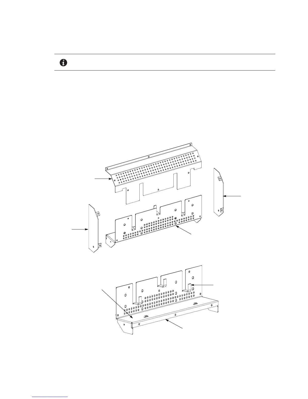
Figure 4-5. UPS Power Terminal Cover Parts
NOTE Wiring can be installed between the UPS and accessory cabinets by using conduit
or by routing wiring through the power terminal cover base wiring channels.
Right Side
Left Side
Top
Base
Conduit Landing for AC Input, Output,
and Bypass, DC Input, and REPO.
(Install conduit to bottom of plate.)
Wire Hooks
Base (Inside View)
 Loading...