UPS System Installation
Eaton 9E UPS (40–60 kVA, 208/220V) Installation and Operation Manual P-164000058—Rev 4 www.eaton.com/powerquality 4-23
6. If using a normally-closed REPO switch, connect a jumper wire between pins 3 and 4 on the REPO
terminal block.
7. If you are installing multiple REPO switches, wire additional switches in parallel with the first REPO.
8. If required, install wiring from the REPO switch to the trip circuitry of the upstream protective devices. A
second contact block is provided on the REPO switch for this function (see Figure 4-18). The REPO switch
wiring must be in accordance with NEC Article 725 Class 2 requirements.
9. Reinstall the interface terminal cover using the retained hardware.
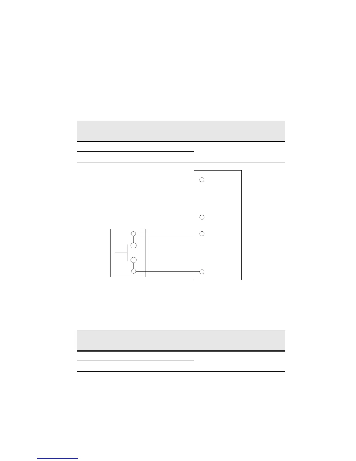
Figure 4-20. Normally-Open REPO Switch Wiring
Table 4-4. Normally-Open REPO Wire Terminations
From REPO Station(s)
Switch Contact Block
(Either Block)
To REPO Terminal Block
on Back of UPS Cabinet
Wire Size Tightening Torque
3 NO 3 Twisted Wires (2)
1422 AWG
(0.754.0 mm
2
)
7lbin
(0.8 Nm)
4 NO 4
Table 4-5. Normally-Closed REPO Wire Terminations
From REPO Station(s)
Switch Contact Block
(Either Block)
To REPO Terminal Block
on Back of UPS Cabinet
Wire Size Tightening Torque
3 NO 1 Twisted Wires (2)
1422 AWG
(0.754.0 mm
2
)
7lbin
(0.8 Nm)
4 NO 2
3
1
2
4
3
4
REPO
Switch
(NO)
Twisted
Wires
REPO TB
NOTE REPO switch rating is 24 Vdc, 1A minimum.
NOTE The REPO switch must be a latching-type switch not tied to any other circuits.
 Loading...