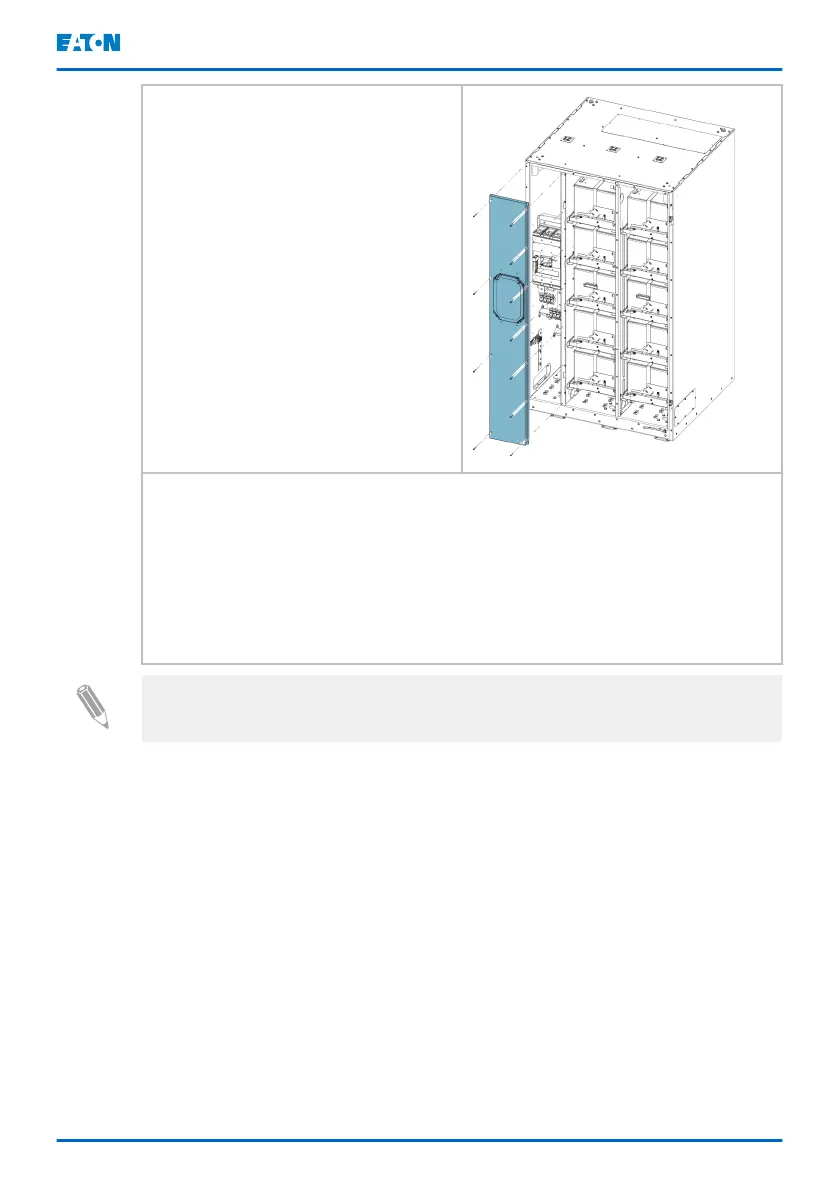
2. Remove the panel on the left.
3. Route the signal wires and power cables through the through hole of
your choosing. See Figures
5
,
6
and
7
for more information.
4. Apply suitable protection to protect the wiring from the sharp metal
edges.
5. Connect the signal wires and the power cables to the connectors
according to Figures
8
,
9
,
10
and
11
.
6. Put the front plate back and fasten the screws.
Note: For safety reasons connector X1 is disconnected during transportation.
Connect it before operating EBC-G.
The battery plus and minus lines of two battery cabinets can be connected
together (daisy chained) and the parallel cabinets can be connected to the UPS
with one set of wires. The protective bonding wires from each cabinet are
connected directly to the ground terminal of the UPS. Note that the service
operations of the battery cabinets are limited, as a single cabinet cannot be
completely isolated while the system is running. For more flexibility, a separate
DC distribution cabinet is recommended.
To daisy-chain signal wires, remove the connector and possible extra length
from the signal wire of the daisy chained cabinet and connect the cables to TB2
terminals. For the TB2 terminals, see Figures
10
and
11
.
Eaton 9PHD Accessory Cabinets TFC-A, EBC-F
and EBC-G User's and installation guide
©
Eaton Corporation plc 2022. All rights reserved. Document ID: P-164000538 41 (63)
 Loading...