I.B. 17555C
Effective November 1999
Page A1
Appendix A
Table of Contents Page
1.0 Introduction . . . . . . . . . . . . . . . . . . . . . . . . . . . . A1
2.0 General Description. . . . . . . . . . . . . . . . . . . . . . A1
3.0 Installation . . . . . . . . . . . . . . . . . . . . . . . . . . . . . A1
4.0 Wiring and Setup . . . . . . . . . . . . . . . . . . . . . . . . A3
5.0 Application Consideration . . . . . . . . . . . . . . . . . A6
6.0 Drawout Operation. . . . . . . . . . . . . . . . . . . . . . . A7
1.0 INTRODUCTION
Appendix A describes the Drawout Case option for the
Digitrip 3000 Protective Relay. Table lists the Drawout
Case versions.
2.0 GENERAL DESCRIPTION
The purpose of the DT3001 is to allow the device to be
removed from gear, using a “quick disconnect” type strat-
egy. The Digitrip 3001 Drawout Relay maintains the same
electrical and operating specifications as the standard
Digitrip 3001 (see pg. 17), with the addition of the follow-
ing Drawout connector specifications.
The Drawout Outer Case consists of two assemblies, a
molded plastic outer flange with “quick release” actuators
and locking mechanism, and the aluminum housing with
terminal blocks.
The Drawout terminal blocks features self-shorting, or
short-before-break contacts, for ct connections that main-
tain circuit continuity when the device is removed. These
self-shorting contacts will prevent damaging voltages
from existing across the current transformer windings.
The terminal blocks feature a 2-stage disconnect opera-
tion. Removal of the DT3001 Inner Chassis will discon-
nect the trip circuits and short the ct secondaries before
the unit control power is disconnected. Upon insertion of
the Inner Chassis, the control power connections are
made before the trip circuits are activated.
This feature
provides added security against false tripping.
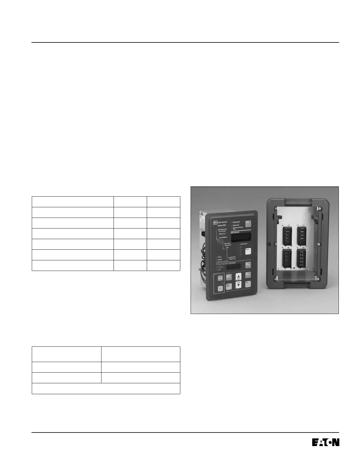
Fig. A-1 Digitrip 3001 Drawout Relay
3.0 INSTALLATION
NOTE: The following material replaces section 5-4,
on page 35.
3.1 PANEL PREPARATION
When mounting the Drawout Case in a panel, it is neces-
sary to prepare a cutout for the device per Fig. 5-1 Cutout
Dimensions
. If a standard IQ cutout exists, no additional
panel setup is required; the Drawout will mount in the
existing 6-hole cutout.
TABLE A-1 ORDERING INFORMATION
Description Cat. No. Style No.
Digitrip 3000 Drawout Relay DT3001 4D13124G11
Digitrip 3000 Drawout Inner Chassis DT3001-IC 66D2001G01
Digitrip 3000 Drawout Outer Case DT3001-OC 66D2005G01
Digitrip 3030 Drawout Relay DT3031 4D13124G04
Digitrip 3030 Drawout Inner Chassis DT3031-IC 66D2001G04
Digitrip 3030 Drawout Outer Case DT3031-OC 66D2005G04
TABLE A-2 ADDITIONAL SPECIFICATIONS
Make/Break Rating 10 A @ 240 Vac nominal
0.25 A @ 280 Vdc maximum
Terminal Wire Gauge No. 14 to No. 10 AWG
Screw Torque Requirements 18 inch-pounds
Meets ANSI C37.90.2 (1995) to 28
V/m.
 Loading...


